@Lohengrimas So to start I'd recommend measuring the rectifier output without the board attached. With no filter cap in the circuit the + and - output will measure 75% less than the usual value, but you can confirm polarity.
There is so little to go wrong otherwise, I can only imagine you mixed up V++ and V-- connections between the rectifier and mainboard.
Richard
Thanks Richard. Reverse voltage was my first guess to: I measured the rectifier output and get around 11.88 at V++ and -12.13 at V--. Measuring near full claimed voltage on the transformer is bad, right?
Without the VSPS attached, ~12 V is about right. It will increase up to about 17 V if you attach some filter capacitance.
The question then is did the wire from "+" on the rectifier board correctly end up at the VSPS board "V++" or did somehow COM/V++/V-- get mixed up. This is the only error I can imagine. And one which happens far more often than I ever thought possible.
The question then is did the wire from "+" on the rectifier board correctly end up at the VSPS board "V++" or did somehow COM/V++/V-- get mixed up. This is the only error I can imagine. And one which happens far more often than I ever thought possible.
Last edited:
Without the VSPS attached, ~12 V is about right. It will increase up to about 17 V if you attach some filter capacitance.
The question then is did the wire from "+" on the rectifier board correctly end up at the VSPS board "V++" or did somehow COM/V++/V-- get mixed up. This is the only error I can imagine. And one which happens far more often than I ever thought possible.
No - but i think I found a little evidence for a short between ground and V++ in the first build - I've since replaced the caps and regulators.
However, still no luck on power on, and the led-light doesn't come on.
The LED remains off, even with +12 V on rectifier output? I guess that's the first thing to deal with.
I suggest disconnecting the VSPS from the power supply, and temporarily soldering two small electrolytic caps (whatever you have) between + and (com) and (com) and - of the rectifier board. Check there is about 32-34 V between + and - and the LED light comes on. There's little to be gained hooking up the VSPS board until you can get back to the point where you know for sure the power supply is functional.
A short between V++ and ground would not damage anything on the VSPS board, certainly not the caps. It would normally just cause the fuse to blow, perhaps melt a trace or smoke a diode or two.
The LED remains off, even with +12 V on rectifier output? I guess that's the first thing to deal with.
No, the led pops up fine when disconnecting the VSPS board.
But the main fuse doesn't blow with the board connected? And no smoke? Still... it does seem like some sort of at least partial short on the VSPS board.
What is the voltage on V++ and V--? How about on pin 4 and 8 of the op amp?
No- the fuse stays put. Can't get a reading any further downstream than the mains.
Hi Richard. I solved the problem with my PSU for the VSPS 300, But I still missed dynamics and transparens to the sound. I found that when I removed the two 100uF el-lyt capacitors on each +/- supply rail. Those between the regulator and the Riaa amp. I replaced them with a 1uF Vima cap. The all transparency, detail and dynamics came back. I need to experiment more with capacitors, because the sound also became forcused on the highfrequency, bass lost its weight, but now I know what caused the lose of sound quality, bad capacitors. I guess I will end op with more cap types in parallel.
@Hylle
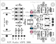
So the ones in pink here?
It wouldn't surprise me to learn that the sound is quite sensitive to those caps, as the X-Reg is such a high feedback regulator, there can be odd interactions.
Early on in the development it crossed my mind to "have the courage of my convictions" and run the X-Reg straight into the opamp with minimal capacitance, but I wimped out in the final design and added the 100uF x4 banks per rail. The problem was that previously (not with the X-Reg, but LM317 etc) I found, as you did, that the bass loses all weight when those caps are removed.
Please keep us updated with your experiments.
Attachments
Last edited:
Some details are coming back to me now. The VSPS300 came out just after I stopped using MM cartridges, so I did not do extensive work with the boards myself. They were based directly on the Phonoclone 3, and adapted from the Phonoclone 3's Eagle files.
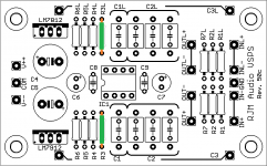
When I removed the unneeded op amp to turn the Phonoclone in to a VSPS, there were 100 uF caps C16,C17 left over that I didn't delete but instead moved over to the remaining op amp, mainly to keep visual symmetry with the four X-reg caps C10-13.
The idea in my head at the time was that C14,15 could be alternatively used for a 0.1 uF ceramic with 2.5 mm lead spacing, as it would fit in the existing package dimensions.
In later revisions of the Phonoclone and VSPS these optional ceramics were added to the layout explicitly, but with the VSPS300 they are "hidden" as a second 100 uF cap. Later I forgot entirely that's what I had intended and just filled the positions with 100 uF electrolytics.
Anyhow: C14 and C15 were originally intended to house 0.1 uF ceramics, at least as a possibility.
Attachments
Last edited:
Yes, it is the pink capacitors that I removed, now I will try an el-lyt together with the Wima film capacitor.
I have used OP134 and now NE5534 opamp. I did not really hear any difference, but it was before I removed the capacitors, so now that the riaa is more detailed I will try the op134 again.
I am supprised of how much those capacitors do for the sound, since the opamps have so much feedback to "clean up" the signal.
I am supprised of how much those capacitors do for the sound, since the opamps have so much feedback to "clean up" the signal.
And PSRR
")
I have now found much better capacitor for the decoupling of opamp supply. A 470uF BC electrolyt with a 10nF orange drop cap in parallel. I guess on should play with a lot of types to find what sounds best in there system. I dont belive in one capacitor or one wire type is the best. You need to find what fits your system, and your taste. Now I consider the riaa finished, especially if I can suppress hum a bit more. Now it is time to build phonoclone, It could be replacement for both the VSPS and the stepup transformer I use.
I think you are hearing not the sound of the capacitor per se., but the sound of the interaction of the capacitor with the X-Reg.
Drop me a pm with your shipping address. I'll send you a pair of Phonoclone 4 boards for you pains. I do not expect the S-Reg on the Phonoclone 4 to give you similar trouble.
Drop me a pm with your shipping address. I'll send you a pair of Phonoclone 4 boards for you pains. I do not expect the S-Reg on the Phonoclone 4 to give you similar trouble.
Transitional BOM for Stereo VSPS 50c
I've also uploaded this to the web page.
This BOM is an attempt to formalize the new VSPS component values. The components are the same as what the 51g boards will use, back-ported to the 50c revision and those original part numbers.
R3/3L changed from 2.21kohms (nominal) to zero
R4/4L changed from 105 kohms to 110 kohms
R5/5L changed from 732 kohms to 768 kohms
Other than having to bother with a shorting jumper, there is no disadvantage to using the old 50c boards. I have about 30 boards in stock left, currently on sale 2 for 1. If you want a larger quantity, I can oblige. Buy one, get as many as I can ship for the same price (probably about 6).
Attachments
I've placed an order for prototype boards for the VSPS 51g (Stereo VSPS with no AW time constant) and something I'm calling 'Emerald' or 'mm/mc phono stage'. These are cheaper boards than the regular production ones I normally stock, 1 oz copper, green.
They'll be a few spares if anyone wants to try the Emerald, or replace their older stereo VSPS. $10 and $5 respectively, boards only.
Richard, I've pm:ed you!
- Home
- Source & Line
- Analogue Source
- The Phonoclone and VSPS PCB Help Desk