Richard. It has been many months since I intervened in the forum.
I have joined the VSPS 300 with x-reg; with resistor values 732k and 105k; and Allen Wright curve.
I am very satisfied with his performance, to the point that I am using it with a Marantz PM6006 amplifier that already has a phono preamplifier included. But the VSPS 300 has more pleasant sound.
The question: What is the reason for which the X-reg has been replaced; the resistors for 768k and 110k and sa have eliminated the Allen Wright? curve.
Finally, I have measured volts in + and - of the IC and it is not exactly the same. Does this influence anything ?.
Greetings from Uruguay, South America. (The other side of the world)
Hi,
1. The X-Reg is replaced with the S-Reg because I think the S-Reg is a better, at least conceptually. Looking back on it I find the X-Reg over-engineered.
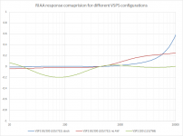
2. The AW time constant is removed because it does nothing useful and people prefer without. The change in the resistors from 105/732 to 110/768 is partly to harmonize the BOM with the phonoclone, and partly to flatten the treble response.
3. The V+ and V- from the X-Reg will not be identical, but shouldn't be more than 200 mV different if you are using 1% resistors. Equal values are somewhat desirable, but small differences don't make an appreciable difference to anything.
Funny you bring up the RIAA values, I've been having a parallel discussion on that and the AW time constant. The upshot is I've decide to change the stereo VSPS circuit to remove it, and change the resistor values to match the VSPS200. It will take a little bit for me to make the necessary updates to the documentation, and the stereo VSPS kits will stay as they are for now but with a note showing that R3 is optional and can be shorted to remove the fourth time constant. (remove is too strong ... technically it moves it up to higher frequencies as noninverting stage cannot manage the treble cut below unity gain)
/R
1. The X-Reg is replaced with the S-Reg because I think the S-Reg is a better, at least conceptually. Looking back on it I find the X-Reg over-engineered.
2. The AW time constant is removed because it does nothing useful and people prefer without. The change in the resistors from 105/732 to 110/768 is partly to harmonize the BOM with the phonoclone, and partly to flatten the treble response.
3. The V+ and V- from the X-Reg will not be identical, but shouldn't be more than 200 mV different if you are using 1% resistors. Equal values are somewhat desirable, but small differences don't make an appreciable difference to anything.
Funny you bring up the RIAA values, I've been having a parallel discussion on that and the AW time constant. The upshot is I've decide to change the stereo VSPS circuit to remove it, and change the resistor values to match the VSPS200. It will take a little bit for me to make the necessary updates to the documentation, and the stereo VSPS kits will stay as they are for now but with a note showing that R3 is optional and can be shorted to remove the fourth time constant. (remove is too strong ... technically it moves it up to higher frequencies as noninverting stage cannot manage the treble cut below unity gain)
/R
Attachments
Richard, thanks for answering my questions. It has been very clear to me.
I have always wanted to power the VSPS 300 with +12 -12 volts.
I will try to make DIY by copying your s-reg circuit and remove the x-reg that is on the VSPS 300 board. I can do it with LM317 and LM337 as well.
I hope not to add noise or interference.These sides do not get good quality components. Resistors DALE no way.
People who have tried the S-Reg +VSPS have reported excellent results.
I expect the "VSPS 400" (VSPS200 phono stage + S-Reg from Phonoclone 4) will happen later this year, if you are interested.
There should be no problem modifying your VSPS 300 boards to use different external regulators if you'd like to experiment. It is best if the regulation is located physically close to the main boards however.
Attachments
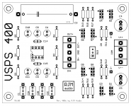
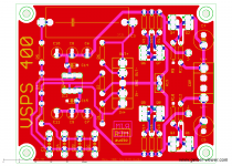
VSPS400c
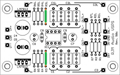
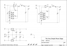
Instead of a copy-paste job from the VSPS 200, I redid the VSPS 400 boards starting from the Phonoclone 4, deleting the first IC stage, and relocating some of the resistors. The "rigorous" ground connection scheme used in the Phonoclone 4 is preserved.
The boards are drop-in replacements for the Phonoclone 4, naturally, and also the VSPS 200 and Sapphire, but are different mounting holes than the Phonoclone 3 / VSPS 300.
Attachments
Rcihard, I think this project is going to be very successful. The VSPS is one of the best phono preamps I've heard for MM. And with this improvement in food will be even better.
I have tried removing the x-reg and feeding it with LM317 and LM337, + - 12volts per lane.
I have noticed improvement in dynamics, and opening in the sound scene (can be subjective) perhaps when increasing feeding voltage.
I think with s-reg it will work perfect.
I wish for success with the project.
I would like to acquire these new kits when they are on sale, but I see the VSPS that I have and I regret to replace them. These kits gave me great satisfaction and I see the great quality of components (DALE resistors, etc).
Greetings.
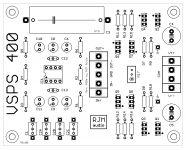
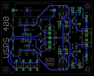
VSPS 400e
Sorry for having to post these updates here. Once the diyaudio blogs are back I won't have to and this can go back to being the help desk.
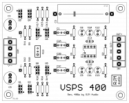
VSPS400e is the final version and has been sent for fabrication. Usual high-grade black/black mask/70 um copper double-sided boards. Anyone interested can pm me. First 5 orders will receive special guinea pig discounts at $15/pr. $25/pr normally. Draft BOM attached.
***
@Dimkasta Early variants of the phonoclone were powered by LM337 LM317 before moving to the X-Reg. So we are going around in circles here to some extent.
Sorry for having to post these updates here. Once the diyaudio blogs are back I won't have to and this can go back to being the help desk.
VSPS400e is the final version and has been sent for fabrication. Usual high-grade black/black mask/70 um copper double-sided boards. Anyone interested can pm me. First 5 orders will receive special guinea pig discounts at $15/pr. $25/pr normally. Draft BOM attached.
***
@Dimkasta Early variants of the phonoclone were powered by LM337 LM317 before moving to the X-Reg. So we are going around in circles here to some extent.
Attachments
@Dimkasta Early variants of the phonoclone were powered by LM337 LM317 before moving to the X-Reg. So we are going around in circles here to some extent.
Yeah, I remember. Subjective comparison is a tricky thing.
I was just wondering because I have had unexpectedly nice results with an improved 317 implementation on a different application
Anyway, I hope to be able to check it on my own soon.
What I have done is something experimental. I have removed transistors and ICs from the x-reg of the VSPS 300 plate.
Then I have provisionally built a DIY plate with LM317 and LM337 with divider and adjustable with variable resistor. I have placed it in the box where the power source is (toroidal 50 watts). + - 12 volts left in each branch.
I have not been able to put it in the preamplifier box for lack of space.
I have noticed improvement in several aspects, although the regulator is not in the preamplifier box.
I think with an s-reg controller it will work better.
I certainly welcome any experiments in this area. Op amps do seem to be unusually sensitive to changes in the voltage regulation circuitry, for reasons that are far from clear.
Although I built several Phonoclones with different voltage regulation over the years, I only ever directly compared the n and n+1 iterations and the regulation was always part of the main boards.
Although I built several Phonoclones with different voltage regulation over the years, I only ever directly compared the n and n+1 iterations and the regulation was always part of the main boards.
VSPS 51e
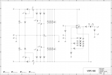
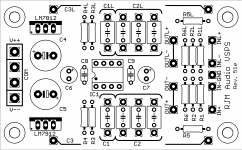
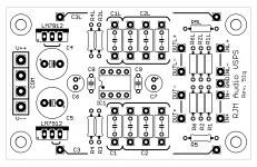
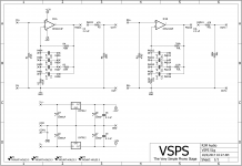
I've re-done the old stereo VSPS board. The schematic is now consistent with the modern versions, and I've updated the grounding and trace layouts too. The wirepads for the power have been changed to the V++/COM/COM/V-- type and enlarged.
I've re-done the old stereo VSPS board. The schematic is now consistent with the modern versions, and I've updated the grounding and trace layouts too. The wirepads for the power have been changed to the V++/COM/COM/V-- type and enlarged.
Attachments
Last edited:
Hi, Richard I have made the resistor changes that you suggested, I have now : -8,37 and +8,67 on opamps.
Ok, progress since the output V+ is expected to be about 8 V. Everything is working as it should, so your evaluation of the VSPS300 will be fair. Do give it a few days to settle in though.
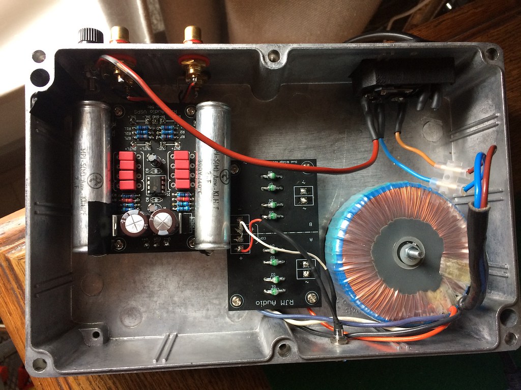
Started this project earlier this month... VSPS with a 12v Sedlbauer transformer. Ordered the boards from Richard (thanks for the great service) and hooked everything up.
 IMG_1986 by ctjr, on Flickr
Unfortunately, things didn't work out too well. I fried one of the regulators and the big capacitors took a beating. I've since replaced the caps and regulators but I still can't get a volt reading at v++ or v-- when I connect the boards. With just the rectifiers and the transformer connected it works fine... Since I'm a total electronics n00b I have no idea what to measure or check, asides from obvious shorts (which I can't seem to find). I'd appreciate any help with the troubleshooting.
IMG_1986 by ctjr, on FlickrUnfortunately, things didn't work out too well. I fried one of the regulators and the big capacitors took a beating. I've since replaced the caps and regulators but I still can't get a volt reading at v++ or v-- when I connect the boards. With just the rectifiers and the transformer connected it works fine... Since I'm a total electronics n00b I have no idea what to measure or check, asides from obvious shorts (which I can't seem to find). I'd appreciate any help with the troubleshooting.
@alpuy Generally all BOM resistor values can be +/- 10% of the listed value, except for the ones marked "RIAA" which should, ideally, be exactly the listed value.
@Lohengrimas That's unfortunate. Despite your insistance that "With just the rectifiers and the transformer connected it works fine." I'm going to have to suggest that maybe things aren't fine with the power supply. If C4 or C4 have blown, that means they saw a reverse voltage. Either you connected V-- to the rectifier positive, or the rectifier positive is, in fact, putting out a negative voltage.
As far as I can tell from the photo, all the parts in both the VSPS and rectifier board seem to mounted correctly. So to start I'd recommend measuring the rectifier output without the board attached. With no filter cap in the circuit the + and - output will measure 75% less than the usual value, but you can confirm polarity.
There is so little to go wrong otherwise, I can only imagine you mixed up V++ and V-- connections between the rectifier and mainboard.
Richard
I've placed an order for prototype boards for the VSPS 51g (Stereo VSPS with no AW time constant) and something I'm calling 'Emerald' or 'mm/mc phono stage'. These are cheaper boards than the regular production ones I normally stock, 1 oz copper, green.
They'll be a few spares if anyone wants to try the Emerald, or replace their older stereo VSPS. $10 and $5 respectively, boards only.
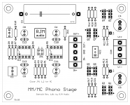
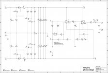
The mm/mc phono stage can be understood as a VSPS with a variable gain head amp connected to the front. This allows both low output and high output cartridges to be used conveniently. The 75 us time constant is moved from the VSPS feedback loop to the interstage, while the board layout and S-Reg regulation are lifted from the Phonoclone 4.
It should be superior as an mm stage than the VSPS, and competitive with the phonoclone as an mc stage. I'm proudest of the layout, which conveniently places the load/gain switch as a single jumper unit in the center of the board.
They'll be a few spares if anyone wants to try the Emerald, or replace their older stereo VSPS. $10 and $5 respectively, boards only.
The mm/mc phono stage can be understood as a VSPS with a variable gain head amp connected to the front. This allows both low output and high output cartridges to be used conveniently. The 75 us time constant is moved from the VSPS feedback loop to the interstage, while the board layout and S-Reg regulation are lifted from the Phonoclone 4.
It should be superior as an mm stage than the VSPS, and competitive with the phonoclone as an mc stage. I'm proudest of the layout, which conveniently places the load/gain switch as a single jumper unit in the center of the board.
Attachments
Last edited:
")
- Home
- Source & Line
- Analogue Source
- The Phonoclone and VSPS PCB Help Desk