Phonoclone 4.0b RJM build mk II
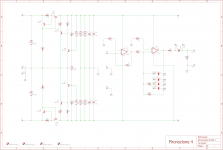
Today I built a fresh pair of phonoclone 4.0b boards and installed them in the old chassis. The component position was stock, but I changed quite a few resistor values.
R11-14 -> 33.2 ohms, reduces source current from 28 mA to about 18 mA.
R15,16 -> 1k
R17,18 -> 6.19k, I had the value on hand, and wanted to reduce V+ to allow the S-Reg inputs to be powered off 12 V supplies if preregulation is found to be needed later. The V+, V- are now 8.45 V.
C3 is 3 uF, as before, as that's the value I have. OPA27 reused from before. I matched Q7 and Q8 between channels to get the S-Reg outputs to be the same for both channels. Last time I had half a volt difference L/R for |V+| + |V-|, this time its 20 mV. I suspect I smoked a transistors last time.
I also replaced the ratty RCA jacks in the chassis, redid the ground wires with heavier gauge, and will wire it up with "extra twisty" 24 AWG solid core copper pairs for the I/O. This is made by unwinding the internal pairs from CAT 5 cables and hand-twisting into a tight spiral. If that doesn't work I'll move to the shielded cable I have, but it's terribly stiff to work with, I hate it.
After checking the DC operation (no issues) I quickly verified that there was no hum visible for a 47 ohm dummy load on the input. I had the case open however so not a final statement, but only as a "so far so good" progress milestone. This stock board layout is no worse than my modified version at least. It's now cooking overnight to settle in.
Tomorrow I will complete the wiring and run noise measurements.
Attachments
All the CAT5 I have used are hard drawn.CAT 5 cables and hand-twisting into a tight spiral. ............. but it's terribly stiff to work with, I hate it.
For the normal twisting that works for audio and lower frequency interferences (<100MHz) it is not a problem.
If you want a spiral with 3 or more Turns/per inch, then go to an annealed copper wire. I use 0.6mm insulated copper hook up wire for signals and lower current power.
While I have a moment, let me try to explain the difference in sound between the phonoclone 3, phonoclone 4 mk I build, and crystalFET.
They are all satisfactory, good even, but taking designer license to be over-critical the crystalFET is too soft, the pc4 is too hard, and the pc3 is too grainy...
The pc4 is, I feel, the closest tonally to what is coming off the cartridge, the main problem is actually its higher noise floor, I can't hear the groove, low level details are obscured by phono stage background noise even though there is no audible noise or hum at the listening volume anymore.
I prefer the CrystalFET at present despite its obvious extra warmth, exactly for it's extra warmth. The pc4 though seems to have more promise, more neutrality and vitality, if I can manage to tame the noise and fill in the lower registers.
That's the status going into the Mk II build.
You didn't say why but I assume work hardening. It's definitely a big problem with the cat5 I use, I would love a good alternative....
This wire may fit the bill.
An externally hosted image should be here but it was not working when we last tested it.
It is a twisted 22g pair with a copper shield by Mogami. The next stage I build will utilize this. A little expensive but you only need a few feet of it. https://www.takefiveaudio.com/categories/87-mogami-cryo-treated-interconnect-speaker-cable I can measure the capacitance if interested.
BTW, can the transformers inject noise into the wiring within the power supply via the unshielded wires used to hook up the rectifiers and the umbilicals? I tried to shield mine as best I could all the way from one bow to the other.
I have just finished my VSPS (stereo, single-board) build and am experiencing both hum and RFI. The unit has a separate box for the PSU connected with a 3-pin jack and unshielded 22-gauge stranded wire. I am using a Triad Magnetics toroidal transformer--at Richard's suggestion, I got the medical-grade version (50VA). Besides the normal secondaries, it has an extra green- and yellow-striped wire for grounding purposes.
I suspect a shielded connection between the two boxes might work better. Before I take the cable apart, however, I would like to consider the transformer grounding. The green safety ground wire is connected to the PSU chassis. Because I wasn't sure how to wire the transformer ground, I attached it to the chassis also, but at the other end of the box, about six inches away. Could current be flowing between the two chassis connections to cause a ground loop? If so, how should I wire the transformer ground? The PSU is otherwise wired exactly as the RJM Audio build guide indicates.
In addition, what are peoples' experiences regarding unshielded triplet power cables and RFI? I plan to solder a small capacitor (220 pF) across the input jacks to help combat RFI in any case.
Any thoughts are appreciated.
When you attach the PE to the Chassis/enclosure that is connected to the mains there is no loop created.I have just finished my VSPS (stereo, single-board) build and am experiencing both hum and RFI. The unit has a separate box for the PSU connected with a 3-pin jack and unshielded 22-gauge stranded wire. I am using a Triad Magnetics toroidal transformer--at Richard's suggestion, I got the medical-grade version (50VA). Besides the normal secondaries, it has an extra green- and yellow-striped wire for grounding purposes.
I suspect a shielded connection between the two boxes might work better. Before I take the cable apart, however, I would like to consider the transformer grounding. The green safety ground wire is connected to the PSU chassis. Because I wasn't sure how to wire the transformer ground, I attached it to the chassis also, but at the other end of the box, about six inches away. Could current be flowing between the two chassis connections to cause a ground loop? If so, how should I wire the transformer ground? The PSU is otherwise wired exactly as the RJM Audio build guide indicates.
In addition, what are peoples' experiences regarding unshielded triplet power cables and RFI? I plan to solder a small capacitor (220 pF) across the input jacks to help combat RFI in any case.
Any thoughts are appreciated.
The mains carrying Chassis has no audio connections.
What is the Transformer Ground? Transformers don't have any grounds.
The transformer could have an interwinding screen, has your transformer got an interwinding screen? If so, then this gets connected to the Faraday cage formed by the enclosure. It is not a ground. It is a Chassis connection to take mains interference to the screening enclosure and it does not create a loop.
The Preamp chassis is a screen (Faraday cage). It too has no audio connections. It is safer to connect this back to the transformer chassis. This safety connection does not create a loop.
Have you connected any of the audio side to either chassis?
Have you fitted any filters to any of the cables entering any of the chassis?
Last edited:
What is the Transformer Ground? Transformers don't have any grounds.
Okay, it sounds like an interwinding screen, which is called a "shield" by Triad. From the datasheet http://www.mouser.com/ds/2/410/media-845720.pdf: "Connections: Transformer is provided with 8” (203mm) long, 0.25” (6.35mm) stripped and tinned, stranded UL 1015 lead wire. Primaries are 22AWG, Secondaries are 20AWG, and Shield is 20AWG. The GRN/YEL shield lead is typically grounded."
Per the RJM build guide, the audio is connected once to the preamp chassis by means of a single wire from the PCB common to a screw point next to the RCA jacks. The other side of the screw is connected to the drain lead from the turntable.
I have not fitted RFI filters on either power or audio yet.
Sorry about no pictures. The boxes are rather crowded and I will need to open them up at both ends to display the contents.
@ChicagoJTW
Please see the construction guide if you haven't already.
I don't think I've ever had someone report hum/rfi in the stereo VSPS before.
The transformer screen (ground as you call it..) connects to the power supply chassis, it doesn't matter where with respect to the earth connection to the mains. Remember that COM does not connect to any chassis directly, just goes from the diodes up to the board through the umbilical. At the phono stage end, the chassis connects to board GND.
Normally this means these is no direct electrical connection between the phono stage chassis and the power supply chassis/earth. You can try making that connection explicitly through the umbilical, but it doesn't usually help.
For RFI a small capacitor connected at the input RCA might be helpful and is worth trying.
Would appreciate photos once you get the chance.
This wire may fit the bill.
(note it appears you can't embed Google Drive links into diyaudio directly)
It is a twisted 22g pair with a copper shield by Mogami. The next stage I build will utilize this. A little expensive (snip)
The link appears to go to someone re-selling Mogami cables that have been "cryo treated" (i.e. dumped in liquid nitrogen?) You can find Mogami 2534 etc. at any pro-audio supply house. It is not especially expensive.
For the record what I'm looking for is hook up wire, preferably solid core, which does not work-harden and has easy to strip insulation and good sonics.
BTW, can the transformers inject noise into the wiring within the power supply via the unshielded wires used to hook up the rectifiers and the umbilicals? I tried to shield mine as best I could all the way from one bow to the other.
I've never had a problem with that and it doesn't make a lot of sense. If you imagine noise from the diode current conduction pulse coupling to the power supply case, the case is earthed so that's the end of it.
In fact the whole idea of leaving COM disconnected from the power supply case is to avoid having a circuit common polluted by the power supply.
I've always used unshielded cable for the umbilical. In rare cases this might be a problem for RFI interference, but other than that it's no big deal.
The link appears to go to someone re-selling Mogami cables that have been "cryo treated" (i.e. dumped in liquid nitrogen?) You can find Mogami 2534 etc. at any pro-audio supply house. It is not especially expensive.
For the record what I'm looking for is hook up wire, preferably solid core, which does not work-harden and has easy to strip insulation and good sonics.
It seemed this wire is flexible, twisted and shielded. That is why I thought it might work for you. I bought about 10 feet from the supplier I linked to. That was my only connection to them.
I've never had a problem with that and it doesn't make a lot of sense. If you imagine noise from the diode current conduction pulse coupling to the power supply case, the case is earthed so that's the end of it.
In fact the whole idea of leaving COM disconnected from the power supply case is to avoid having a circuit common polluted by the power supply.
I've always used unshielded cable for the umbilical. In rare cases this might be a problem for RFI interference, but other than that it's no big deal.
I'm not saying that one needs to shield the umbilicals. I just "thought" that grounding the phono-stage enclosure to the power supply via shielded umbilicals might create a Faraday cage that might reduce RFI or EMI effects. However in light of the pollution issue, I'm going to disconnect the power supply connection and listen for the effects. Sounds good though the way it is!
Last edited:
Technically you are right about the Faraday cage part, the problem is if the power supply chassis is earthed, and the chassis connected to the phono stage chassis, which is connected to GND, which is connected to COM, IN-, and OUT- (all circuit common) and the circuit common is connected to earth somewhere else in the system, say the power amplifier, then you have the classic Faraday cage earthed at two points = ground loop conditions.
Hi Richard, sorry I haven't reposted much lately, been busy. I was able to shield the transformer and I switched to RCA cables I for my signal I/O. I also double checked all my grounding points and simplified duplicate wires. no change so far, I have the same hum. I stopped there and took the case apart to laser etch my end plates. so my progress was halted. should I try these new resistor and capacitor values you changed to?
I am gonna tinker more with it soon. I am tempted to borrow an O-scope from work and try and signal trace the 60hz through the circuit, I just don't know if I'm allowed to bring equipment like that home yet. I am curious.
I am gonna tinker more with it soon. I am tempted to borrow an O-scope from work and try and signal trace the 60hz through the circuit, I just don't know if I'm allowed to bring equipment like that home yet. I am curious.
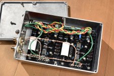
Phonoclone 4.0b mk II
Here you see RJM on his best behavior re. cable dressing, though none of it is shielded, just twist/braid.
And so, not only is there no hum but it sounds way better too. I have no idea why, either, but this version at least delivers what I had hoped for: clear and spacious, fast and dynamic. If it errs at all it is for being a bit too "brassy", but overall it is simply better than previous iterations. Best part is the "non op amp-iness" as sonically there is none of that grit or grain I associate with ICs, so from that point of view the S-Reg shunt seems to doing what it is supposed to be doing.
@Erik I don't see how any of the resistor changes could have made a significant difference to anything, but if you are wondering if I have any better explanations or advice at the moment the answer is no. All I can report is I have got my S-Reg powered phono stage working without any additional shielding or modifications of the board layout. At this point I'm starting to wonder if it wasn't something associated with solder messiness in my case, where flux or solder got somewhere it shouldn't have.
Attachments
Last edited:
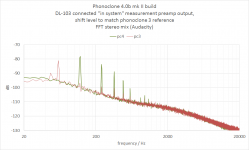
Ah, measurements. At least we see where we are.
A. Not bad, not super. The ripple voltage is visible above the noise floor, about 15 dB or more higher than for the X-Reg powered phonoclone 3. This is audible with the volume all the way up as a small amount of hum/buzz over the background hiss/rush.
I'm conflicted on this. No, on one hand it's not acceptable, but on the other it's really close to being acceptable.
What I will do next, for the purposes of experimenting, is to power the whole thing off a Z-Reg. I fully expect that to banish the hum, but I'm curious about how it will affect the sound.
Attachments
Last edited:
What are the frequencies of the spikes?
50, 100, 150, 200, 250 etc?
The one to the left of 200Hz is about 20dB (10times) worse and the one to the right of 200Hz is about 15dB (5times) worse.
Is the plot of Noise + Hum showing ~1mVpp, or ~0.3mVrms?
The power cables in post3636 are braided. Is it worth re-testing using twisted triplets?
What are the two green cables taken to the bolted chassis connection?
The loop areas of the input/output socket terminations are very big.
Could you do a retest with these made very much smaller?
Last edited:
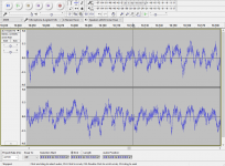
The pc4 FFT trace is from the waveform shown in the screen capture also attached, a 120 Hz triangle wave close to what is seen in the S-Reg power supply, the filter capacitor charging current.
The absolute magnitude cannot be read from the screen capture scale. (long story, I was not going to move my desktop PC over to the stereo system to measure this so I collected the data with my Kenwood digital recorder and scaled it to the noise floor of the pc3, calibrated data I had archived previously) It is estimated at -80 dB, 20 dB above the baseline noise floor.
The absolute magnitude cannot be read from the screen capture scale. (long story, I was not going to move my desktop PC over to the stereo system to measure this so I collected the data with my Kenwood digital recorder and scaled it to the noise floor of the pc3, calibrated data I had archived previously) It is estimated at -80 dB, 20 dB above the baseline noise floor.
Last edited:
- Home
- Source & Line
- Analogue Source
- The Phonoclone and VSPS PCB Help Desk