Thanks for your answer. I didn't have any 10k resistors around so I tried sticking 3k resistors at the bboards inputs. That reduced the offset to about 10 and 70 mV, much better but still a bit high for my taste...
How low a value can I go with those resistors? Would it be preferable to just go for coupling caps at the bboards outputs? Or both?
Thanks again for your assistance!
Skickat från min Nexus 5X via Tapatalk
How low a value can I go with those resistors? Would it be preferable to just go for coupling caps at the bboards outputs? Or both?
Thanks again for your assistance!
Skickat från min Nexus 5X via Tapatalk
Since the resistor is also the load for the op amp, you probably don't want to go below 5k.
I recommend 10k-25k, and expect the offset to be about 100-200 mV. It is high but inevitable from the design choices at play in this particular config. What you can do, however, is move the bboard circuit to insert it into the circuit in place of R6 on the VSPS. That's the best way to do it, but since it is application specific it's not part of the default instruction set.
Remove R6, and connect wires off-board from the pads to and back from the bboard.
The output offset will of course be zero. Internally it will also be quite small since the DC impedance seen by the bboard input is now directly the output Z of the op amp, so zero ohms essentially.
Thanks Richard, that is really helpful, now I understand fully what was going on.
I did finally try a 10k resistor in place of R7 (still about 200-300 mV DC), and a coupling cap (+ discharche resistor) at the bboard's output, and that did the trick. That is my config right now, it sounds fine, but it looks very temporary and messy (coupling cap and resistor soldered on the outputs RCAs haha!...).
Your suggestion is clearly the most elegant way to solve the problem, and would also make things tidier as far as cable routing is concerned. It will be next weekend's project!
C
Leave the pot adjuster to as late in the reproduction chain as possible. It is usual to put the adjustment pot as the last stage before the power amplifier.
If there is a risk of clipping earlier in the chain then you have too much gain. It is the excess gain that needs to be altered, not attenuate after too much gain.
If there is a risk of clipping earlier in the chain then you have too much gain. It is the excess gain that needs to be altered, not attenuate after too much gain.
Thanks Andrew.
I was thinking of putting a selector switch, then a volume pot, before the buffer stage to make the unit a buffered passive preamp with mc phono onboard.
Then again I am open to turning it into phono preamp with volume control if putting the pot at the end of the chain improves the sound.
I was thinking of putting a selector switch, then a volume pot, before the buffer stage to make the unit a buffered passive preamp with mc phono onboard.
Then again I am open to turning it into phono preamp with volume control if putting the pot at the end of the chain improves the sound.
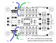
So... I did get an hour to kill, so I did the suggested "re-arrangement", and I'm glad to report everything is fine, offset's gone!Should go something like this.
As long as the COM is in electrical contact with COM on the VSPS there is no need to connect the bboards IN- and OUT- terminals. The bboard GND would not normally be connected.
That did really clear the wiring a bit, since I could loose the minus polarity wires back and forth from the b-boards. And I could shorten the output wires since it all comes from the VSPS now, which is located closer to the connectors.
If anything, i seem to hear a tiny bit less of hum, when listening to the background noise with phones. Not that it was any audible before at listening volumes...
All in all, a really nice project as it turned out!
Skickat från min Nexus 5X via Tapatalk
Last edited:
@CHiroshi
That's for reporting back and confirming the hum was better. I was a little unsure of how it would turn out.
@cromodora
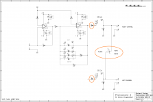
In principle C3 is shorted over, and R7 is replaced by the volume control, which then feeds the bboard through a DC blocking cap and 10k input resistor.
R8? Trick question - there is no R8 in the VSPS circuit!
That's for reporting back and confirming the hum was better. I was a little unsure of how it would turn out.
@cromodora
What about Phonoclone boards feeding a buffer board through a pot in the same enclosure.
What values should R8 and R7 be if we omit C3 as there are already input caps and impedance is set at 10KOhms on the buffer board?
In principle C3 is shorted over, and R7 is replaced by the volume control, which then feeds the bboard through a DC blocking cap and 10k input resistor.
R8? Trick question - there is no R8 in the VSPS circuit!
Hello Richard,
Sorry to bother you with a basic question like this. I am seriously thinking about buying a phonoclone kit
I have a Lyra argo low output mc cartridge and was wondering if it is suitable for use with the phonoclone.
The specs are;
Internal impedance = 4 ohms
Output voltage = 0.45 mV
I believe from what i have read that lyra carts do not have the most even of frequency responses with a boost in the high frequencies.
I do hope this would not cause a problem if used with a phonoclone.
Many thanks, Stuart ( UK).
Thanks for the reply Richard and resistor values.
Looks like i will go ahead then.
My source is a LP12 and the phonoclone will be going into a zero feedback, single ended transistor, transconductance preamplifier. (if that makes any sense).
Do you have the phonoclone kits in stock ?
Many thanks, Stuart
Looks like i will go ahead then.
My source is a LP12 and the phonoclone will be going into a zero feedback, single ended transistor, transconductance preamplifier. (if that makes any sense).
Do you have the phonoclone kits in stock ?
Many thanks, Stuart
My source is a LP12 and the phonoclone will be going into a zero feedback, single ended transistor, transconductance preamplifier. (if that makes any sense).
I can pretty much guess the general type, yes, though I admit to this day I don't really understand what makes a transconductance amp a transconductance amp.
yes, the PC3 kits are available currently
Increase R8 from 47 ohms to 4k7 ohms and then add a switch to connect OUT+ of R and L channels together.
The price you pay is slightly higher output impedance (4k7 ohms) even when the MONO switch is open, but there are no free lunches... that's why it's usually implemented in the preamp input section.
The price you pay is slightly higher output impedance (4k7 ohms) even when the MONO switch is open, but there are no free lunches... that's why it's usually implemented in the preamp input section.
Increase R8 from 47 ohms to 4k7 ohms and then add a switch to connect OUT+ of R and L channels together.
The price you pay is slightly higher output impedance (4k7 ohms) even when the MONO switch is open, but there are no free lunches... that's why it's usually implemented in the preamp input section.
Sounds doable, should that circuit be at the input or output of the phono stage? Any chance of a sketch? I assume 4k7 ohms is the same as 47k ohms?
Thanks in advance.
the k is used instead of a decimal point.
so 4k7 = 4700ohms
47k = 47000ohms
0r2 1/5th of an ohm
2r2 = 2 and 2/10ths of an ohm.
Fit the mono switch after the 47k at the output. that's where you have to swap the two 47r to 4700r
But you must use a very short cable and very low value of RF filter at the input to the next stage.
Far better to fit the mono inside the line level pre-amp.
[what Andrew said]
1m interconnects should be fine, and input stages often don't have an RF filter or if they do have 10k in series with it anyways, so the 2k~ this mod adds to the output impedance shouldn't make much difference.
1m interconnects should be fine, and input stages often don't have an RF filter or if they do have 10k in series with it anyways, so the 2k~ this mod adds to the output impedance shouldn't make much difference.
Attachments
Last edited:
Hello Richard
After a loooooong time I have some spare time and I wanted to play with the VSPS a bit.
However my boards are really tired. I have already lifted 3 or 4 pads.
I wanted to build a pair with some more beefy pads to try different capacitors, resistors and different regulation.
I remember you mentioning that you have a version of the pcb that includes the bypassing ceramic caps.
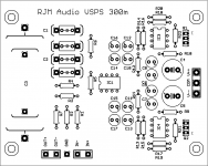
Are those files available somewhere? The ones on your site are the 300m version that does not include those caps.
Thanks again
After a loooooong time I have some spare time and I wanted to play with the VSPS a bit.
However my boards are really tired. I have already lifted 3 or 4 pads.
I wanted to build a pair with some more beefy pads to try different capacitors, resistors and different regulation.
I remember you mentioning that you have a version of the pcb that includes the bypassing ceramic caps.
Are those files available somewhere? The ones on your site are the 300m version that does not include those caps.
Thanks again
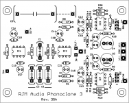
You are probably thinking about the phonoclone3 boards, which I redid with optional bypass caps C17-20 and extra pads to tap off the X-reg output V+, V-. The VSPS never got that treatment...
If you want to use bypass caps though just use C14,15 for that purpose. C16, C17 can still be used for 100 uF electrolytics. Functionally it amounts to exactly the same thing as the arrangement on the phonoclone boards.
If you want to use bypass caps though just use C14,15 for that purpose. C16, C17 can still be used for 100 uF electrolytics. Functionally it amounts to exactly the same thing as the arrangement on the phonoclone boards.
Attachments
- Home
- Source & Line
- Analogue Source
- The Phonoclone and VSPS PCB Help Desk