(330+560)/2=445
I gave 400 as a good value to use with both of your carts. Its not exact - no need to be - but if you are having issues it's better to run on the low side.
The main point is to use something substantially smaller than 1k. If you already are and still have hiss/hum pm me and I'll try to help you out.
/R
I have finished assembly of my VSPS 300m.
The voltages between IC1 pin 4, G and 7 are 10.4V on both boards.
V++ V-- is 37.3V in both cases. Is it still within spec?
The PSU design specifies 250mA fuse. Upon power up I kept blowing the fuses of my 50VA toroids, feeding the GBPC3506 bridges. I have uprated the fuses to 300mA (my IEC socket fuses both load and neutral with separate fuse). I'm waiting for the delivery of "big" KBPC5010 bridges Richard recommended in one of his posts.
I have kept the amp powered up practically non stop for the last 48 hours.
It sounds wonderful. Most noticeable is the width and depth of the sound stage. Combined with detail and sonic precision, it reveals instruments with startling presence.
I'm very pleased with the end results.
Congratulations Richard!
You're welcome.
I should really sort out the fuse. Not being a professional electrician I don't know what the correct value and type should be. Looking over some commercial preamp schematics, 500 mA (europe) to 1A (america) would seem appropriate, I should probably update the documents to specify a higher value.
If you are running at 100-120 VAC, try using 1 A fuses. Lower values normally work though, at least they do if they are "slow blow" types that wont trip on the inrush currents.
Richard
transformers and motors and similar highly inductive loads need a fuse during start up that is rated as:
T rated fuse = 3 times transformer VA / Mains voltage.
For a 50VA transformer this comes to 1.3Aac on 115Vac.
Use a T1.25A fuse.
But this size of fuse does not offer the protection given by a close rated fuse.
A close rated fuse is is given without the extra 3 times factor i.e.
T rated fuse = Transformer VA / Mains Vac
Very small transformers have a lot of very thin primary wire. This gives a high primary resistance. This primary resistance acts as a soft start current limiter. But even 50VA benefit from some added resistance to allow reliable starting with a close rated fuse.
Measure your primary resistance.
The start up primary current transient can be as high as:
Ipk <= Vac*sqrt(2) / {primary resistance + cabling resistance + mains source impedance}.
I use soft start on 160VA 230Vac transformers. T800mA fuse and 140r of soft start resistance
Last edited:
Thanks Andrew,
I didn't realize it scaled with transformer VA and not circuit current draw. Unfortunately that makes it difficult to make a blanket recommendation as people tend to use all kinds of different sizes.
Is there any safety concerns with using soft start fuses on the AC? If not then that seems to be the answer. Its only when people use fast fuses that I get reports of them blowing from inrush currents.
T rated fuses will blow if they cannot tolerate the heat generated during that very high transient current during transformer start up.
Thick wire in a "too big" fuse will survive. But that does not offer the same protection as thin wire.
that is effectively what using the 3times factor is doing. It is replacing the thin wire of a close rated T fuse with a thick wire T rated fuse.
Thick wire in a "too big" fuse will survive. But that does not offer the same protection as thin wire.
that is effectively what using the 3times factor is doing. It is replacing the thin wire of a close rated T fuse with a thick wire T rated fuse.
@RJM - i am planning to make VSPS 50c for its simplicity but on single-sided pcb. should i connect COM(connecting decoupling caps 100n and electrolytic) and signal GND together creating common ground plane on the pcb or wire them separately going to a star ground or main transformer/powersupply gnd.
tnx.
tnx.
@wertz a common ground plane on the board itself is the best way to go. Take care with the layout though. Star ground is not needed or even desirable, but you want to make sure the noninverting returns connect to the inverting returns, then the output, and finally the supply returns. The chassis GND can tap into that where-ever, I usually do it at the point where the power supply returns meet up with the output returns.
@Andrew I have never seen such instructions in the diyaudio store, so I can't comment. My concern re. slow fuses was that the would not be fast enough to prevent injury to humans, even if they were fast enough to protect components. I will anyway update my own instructions to recommend 0.5A for 220V and 1A for 110V.
@Andrew I have never seen such instructions in the diyaudio store, so I can't comment. My concern re. slow fuses was that the would not be fast enough to prevent injury to humans, even if they were fast enough to protect components. I will anyway update my own instructions to recommend 0.5A for 220V and 1A for 110V.
thanks for the reply. here is the modified version i made. i removed the regulator section because im planning to use batteries or power bank, modified the C3 trace to accomodate a capacitor i already have at hand. is the ground connection right? and what other corrections i need to make.
thanks.
thanks.
Attachments
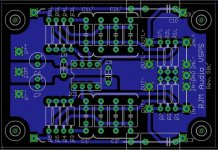
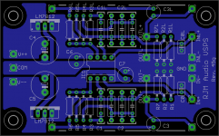
VSPS45g was a early single-sided version of the current boards, I include it for general reference ... I think you have it already, since your version is essentially the same but with the regulators removed.
Attachments
Last edited:
Hi Richard et al,
I purchased the VSPS a couple of months ago and commenced assembly last week. I soon discovered some disparities between the BOM on the phonoclone website and the items that were supplied. I have searched for updated information regarding component values but have not been able to locate any. Is anyone able to provide a list of components and respective values for the VSPS? The stickies at the beginning of the thread are now dead, could they be updated???
Cheers,
Tim
What disparities?
The kit comes with instructions and a parts list. As long as the parts you receive match the list you are good to go.
If they don't let me know and I'll send you the right parts right away.
That may be the problem...I don't have the instructions or part list (not sure if they came with it or I have lost them as it was a couple of months ago!) could you please provide me with them (again)?
Cheers,
Tim
That may be the problem...I don't have the instructions or part list (not sure if they came with it or I have lost them as it was a couple of months ago!) could you please provide me with them (again)?
Cheers,
Tim
Just FYI, there's a difference between the VSPS and the phonoclone. If you are looking at the BOM for phonoclone and working on the VSPS board, you will no doubt be stumped. You should be sure you're looking at the BOM for the VSPS and NOT the phonoclone. Just be certain you are comparing apples to apples.
Carl
VSPS on stripboard
Sorry to interrupt your conversation here.
Recently a friend of mine gave an old inexpensive Sony turntable (I know, it's a crappy one) and i decided to build a stripboard version of vsps according to the instructions on this page. (of cource the dc capacitors where ommited as i've build a seperate psu)
Sound came out just as soon as i powered up the board, BUT, bass is missing and treble is too crisp.
I used the suggested values for resistors (metal film ones) but i am not sure on the capacitor types, as it was hard for me to find the ones shown in the photo.
Maybe I misread some values on capacitors (pF for nF), the thing is that my vsps is no good. Grounding is quite good, humming is inaudible, psu is a basic one as recommended on vsps site.
I need your help, I mean a guide, to troubleshoot my build as I am planning to upgrade my turntable,IF my build performs better.
What should I look for?
Is it due to the bad turntable?
Is it a wrong capacitor type?
Is it a wrong value on a component?
We have a hard time in my country right now, so I cannot order on of RJM's kits.
Thanks for help.
Last edited:
- Home
- Source & Line
- Analogue Source
- The Phonoclone and VSPS PCB Help Desk