What to do with two op-amps powered by one regulator? Use four bypass caps, two for each op-amp?
I always use one bypass cap directly situated by the regulator and for every chip the own caps nearby the chips. This will result in 6 caps per channel.
I always insert some ferrite beads situated direct in front of the bypass caps, this has two advantages:
- you can lead the voltage over this beads, building a bridge and therefore easing the layout of the pcb
- the resulting LC LPF makes the amp very "handy proof", a cellular phone working nearby the amp does not disturb, when you use shielded in- and outputcable and a metal enclosure.
As the overall capacitance is quite high, it is good practice to add two protection diodes nearby the regulator. You may have a look at the datasheet of the LM317.
Franz
I worked on my double mono phonoclone and did not get it work with the AD797 as input chips.
No sound at all out of a Denon DL103, with or without input resistor. And very picky to adjust to zero output bias. With the sound generator and the scope, everything worked fine.
After replacing the AD797 by OPA227 (in front of OPA228), the amp is working perfectly.
The noise level is now absolute dead even at full power. The soundstage is still a little bit more living than before with the dual opamp solution (opa2227) with just one tranny.
This will be my consolidated RIAA pre, after adding main switch, LED's and a fuse.
Franz
Attachments
Franz,
The AD797 would have probably needed more attention to bypassing to get it to work, since the bandwidth is so much higher than the OP27 etc. electrolytic capacitors by themselves would be insufficient. The datasheet suggests a combination of ceramic, tantalum and a series resistor.
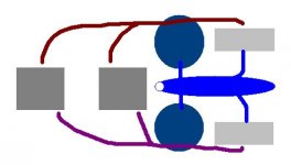
Speaking of bypassing, I agree that 6 capacitors is the textbook-correct, surest method. However, I think in the present case the op-amps and regulators are all so close to each other it is possible to do it with two only, if I try a little harder to fit everything snug on the PCB.
The plan is to achieve something like the diagram below.
The AD797 would have probably needed more attention to bypassing to get it to work, since the bandwidth is so much higher than the OP27 etc. electrolytic capacitors by themselves would be insufficient. The datasheet suggests a combination of ceramic, tantalum and a series resistor.
Speaking of bypassing, I agree that 6 capacitors is the textbook-correct, surest method. However, I think in the present case the op-amps and regulators are all so close to each other it is possible to do it with two only, if I try a little harder to fit everything snug on the PCB.
The plan is to achieve something like the diagram below.
Attachments
phonoclone for different carts
RJM,
I am wondering what would be the best way to make a phonoclone so that I can change resistors to allow using a phonoclone with carts that have very different impedences (6ohms or 8ohms vs 33ohms) but with similar outputs (0.4mv).
Would this mean a compromise in sound?
Thanks.
kn
RJM,
I am wondering what would be the best way to make a phonoclone so that I can change resistors to allow using a phonoclone with carts that have very different impedences (6ohms or 8ohms vs 33ohms) but with similar outputs (0.4mv).
Would this mean a compromise in sound?
Thanks.
kn
I'd keep R1 fixed at some nominal value or zero.
I'd use 3 or 4 resistors in parallel for R2, with jumpers connecting all but the largest value into the circuit. Connecting jumpers reduces the net value of R2 and lowers the gain.
I'd probably avoid using trim pots or long lead wires connecting front panel switches.
/R
I'd use 3 or 4 resistors in parallel for R2, with jumpers connecting all but the largest value into the circuit. Connecting jumpers reduces the net value of R2 and lowers the gain.
I'd probably avoid using trim pots or long lead wires connecting front panel switches.
/R
I am wondering what would be the best way to make a phonoclone so that I can change resistors to allow using a phonoclone with carts that have very different impedences (6ohms or 8ohms vs 33ohms) but with similar outputs (0.4mv).
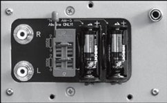
John Atwood's Artemis phono stage uses a zif socket
John's stage has been very well received, so I could argue that it won't mean a compromise in sound.
Attachments
Hi Pjotr...John Atwood probably bought them all up...But I cannot find a 10 way zif socket easily.

John's stage has been very well received, so I could argue that it won't mean a compromise in sound.
Unfortunately its not quite that simple. The resistors plugged into that external socket are probably just setting the catridge load. kn wants to switch R2 of the phonoclone, which is the feedback resistor of the first stage. The socket itself isn't the issue, any switch or socket arrangement would be acceptable... the problem is the long lead wires / traces associated with moving the resistor away from the op-amp.
Also, I wouldnt be all that happy about having R2 unshielded and external to the rest of the circuit.
/RJM
Correct.The resistors plugged into that external socket are probably just setting the catridge load.
Richard
a pretty layout, but again my question:
Does it make sense, to use single opamps but common bypass caps for both chips?
My answer (imho): No!
For this power supply, you could use dual opamps, just the thermal stability will decrease theoretically. But there is no thermal problem within this circuit.
Just my two cents.
Franz
Hi Franz,
I agree with you, in principle. And it could be done: either by moving to a double-sided PCB with a ground plane or adding a circular ground ring (U-shape) at the edges of the single-sided layout.
But please have a look at the layout again. The distance between the capacitor and the output op-amp is about 2 cm. The distance between the capacitor and the voltage regulator is also about 2 cm. The input op-amp, meanwhile, is 5 cm away. The traces are extremely wide, over 1 cm typically.
At the frequencies where the electrolytic capacitor is functionally useful as a bypass element, up to 200-300 kHz perhaps, I would say that these dimensions are still "close enough". At Mhz frequencies, where "close enough" is now a matter of millimeters not centimeters, the only solution I see is to add ceramic or tantalum caps right next to the op-amp pins, with the return at the OUT- pad. Electrolytics won't be effective, and moving them a couple of centimeters one way or the other doesn't change that. Fortunately the bandwidth of the circuit is sufficiently low (100-200 kHz usually) that electrolytics work just fine. (AD797 and possibly OP37 excepted)
Remember that in addition to having high inductance, electrolytic capacitors also have resistances of, say, 200 to 500 mohms for the values typically used in these circuits. So, while I can appreciate that an CRC filter can be set up between the regulator and the load to reduce power supply noise, in practice the trace resistance, with or without a ferrite bead, isn't sufficient to generate any useful filtering or isolation unless the electrolytic capacitors are themselves bypassed with low inductance ceramic ones, for example, or a resistance of 10 ohms or so is deliberately added as the "R" in CRC. (Something I've been thinking of at least testing...)
The 5 cm distance from the input op-amp is borderline, I realise. Its a compromise I'm willing to live with, but I'll have a look at adding a ground plane and some flexibility in the bypassing options in order to satisfy as many of you as possible.
My 2.2 cents ( my thoughts are only available in 10% tolerances! )
/R
Attachments
rjm said:Here's what a double-sided PCB would look like, with six bypass caps.
But does it make you feel happier?
/R
Could THAT design be altered for a dual op-amp? I would LOVE to build 2-3 (1 for me, 2 for friends) of those as stereo boards..
rjm said:Here's what a double-sided PCB would look like, with six bypass caps.
But does it make you feel happier?
/R
It would make me feel happier if the whole back side was a ground plane like in one of your earlier posts. It would function as a bit of a shield and would allow placement of other electronics a bit closer to the board. What would the cost difference be to do this versus the single sided version?
Edit: Here's the prior post I was referring to. It should also help a bit with any possible noise issues.
http://www.diyaudio.com/forums/showthread.php?postid=792618#post792618

- Home
- Source & Line
- Analogue Source
- The Phonoclone and VSPS PCB Help Desk