Just a quick follow up concerning my VSPS300 build.
I've mounted the VSPS boards in a metal enclosure, I mounted a male XLR socket at the back.
The transformer (EI core) and diode bridge (using the center tap configuration) are housed in a separate enclosure with a 1m umbilical connecting them together.
For practicality, I used an XLR cable I had lying around, hard wiring it on the PS side. (I know it's not ideal, and I plan on building a proper cable with heavier gauge wire as soon as I can)
Problem is, even when the PS is not connected to the VSPS box, the transformer hums and gets hot over time. The hum starts low and increases steadily over time, until it becomes loud enough to be annoying.
Any idea what the reason could be? knowing that the transformer is rated at 3 amps
Thanks
Nick
thanks RJ. it says it has mic, line-in and S/PDIF-in so i guess it should be fine.
cases have arrived so i should be putting the power supply and phonoclone together this week.
i should have my whole system up and running by the end of the month which will include,
Pink Triangle PT TOO
Denon DL301 MK11
Audiomods Tonearm
Phonoclone Phono Stage
Sapphire Headphone Amp
Beyerdynamic DT880 PRO's
so should be quite a high resolution system.
Picture?
Shorted turns in the x-former?
Incorrect wiring?
DC on the input?
XLR interconnect cable is plenty to pwr such a low draw device. I wouldn't worry about cable loss BUT I would change the connectors from XLR ONLY because someone else may not know you are using it for pwr and not signal. I usually use the 4 or 5 pin CB connectors...
CB Microphone Connectors in the Connectors & Adapters Department at Parts Express | 1578
I don't think so because the preamp fires up and plays very wellIncorrect wiring?
Could be, but then again, how can I check? And how can I address it?DC on the input?
I'll post pictures later on, but it's a pretty straightforward setup with one center tapped transformer and a diode bridge. Center tap goes to Comm and the remaining two wires got to the bridge's AC inputs.
Bear in mind that this happens even when nothing is connected to the PS.
Thanks
Last edited:
Problem is, even when the PS is not connected to the VSPS box, the transformer hums and gets hot over time. The hum starts low and increases steadily over time, until it becomes loud enough to be annoying.
Seems like as the transformer heats up, the losses increase and the mechanical vibration (hum) gets worse.
Toroidal models never get even warm in this application - that's why I recommend them - but laminated types may run into these kinds of problems. It's happened to me before, before I gave up dumpster diving for parts!
I would double check your connections and voltages. If you are sure that everything is working properly, I suggest replacing the transformer.
/R
Last edited:
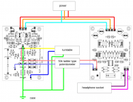
before i go wiring things up i would just like to make sure that i have everything correct. diagram only shows one side.
phonoclone feeding a 50k ladder type potentiometer feeding a sapphire headphone amp.
all grounds to casework, ground not connected to mains earth.
thanks
phonoclone feeding a 50k ladder type potentiometer feeding a sapphire headphone amp.
all grounds to casework, ground not connected to mains earth.
An externally hosted image should be here but it was not working when we last tested it.
thanks
Probably as the revised image, below.
The circuit common of the phonoclone and sapphire boards are automatically connected together, both through the shared power supply COM connection and the signal connection phonoclone out- and sapphire in-. Ideally all this should only connect to the chassis in one place.
I'm not 100% certain where the best place is to make this connection, but the GND pad of the phonoclone board seems to be as good as any.
Where you have the attenuator connected to the chassis, I assume you mean the metal housing only.
Richard
Attachments
Biblo,
if any of the gear is mains powered then you must use PE to chassis somewhere.
Otherwise the mains fuse will not blow when Live contacts other internal parts.
If only one item is PE connected, then all other mains powered items will try to use the interconnects to pass Fault Current to Earth (via that one PE) and thus blow their own mains fuse.
In case somebody is looking for a Phonoclone, i have mine up for sale.
More info here -> http://www.diyaudio.com/forums/swap-meet/208577-rjm-audio-phonoclone-sale.html
thx
More info here -> http://www.diyaudio.com/forums/swap-meet/208577-rjm-audio-phonoclone-sale.html
thx
Biblo,
if any of the gear is mains powered then you must use PE to chassis somewhere.
Andrew,
The power supply is external, hence only isolated, low voltages are passed into the chassis with the boards shown.
What, by the way, is "PE"?
Andrew,
The power supply is external, hence only isolated, low voltages are passed into the chassis with the boards shown.
What, by the way, is "PE"?
https://en.wikipedia.org/wiki/Protective_earth
thanks everyone.
so no need to connect the headphone socket to gnd. the gnd will be connected to casework via the TT gnd binding post.
the power supply box will have the casework connected to PE (power earth as i assume that's what Andrew is on about) with an umbilical only containing 'V++ COM V--' to the pre/headphone being in a separate box will not be connected to PE. i would assume that the gnd pin is just returning back via the com so is essentially a 'live earth'. so nowhere in the chain is anything connected to PE (mains earth) apart from the power supply casework and is only there for safety reasons.
the attenuator has a gnd wire which will be connected to the same gnd as the TT.
both L-/R- headphone socket will be connected together and the L+ and R+ to the other pins on a 3 pin socket.
i'm off out today as it's sunday and my day off so will resume the build on monday.
Last edited:
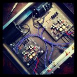
Finally finished my VSPS 300... Now dust off my Knosti washing machine and I'm ready to try my Rega P5 for the first time.
lovely neat build. will be interesting to hear your evaluation on the sound as from what i have read elsewhere people seem to love the sound.
I dunno... I think your coupling capacitors are still too small.Finally finished my VSPS 300.

@MrOnion
Thanks for that link, though the jargon concentration is so high as to be all but unreadable. I got the message though: PE (protective earth) = "the connection formerly known as earth" ...
I dunno... I think your coupling capacitors are still too small.
QFT... wait till you see the new russian teflons I got
In the UK, the correct term is protective earth............. though the jargon concentration is so high as to be all but unreadable. I got the message though: PE (protective earth) = "the connection formerly known as earth" ...
But all lay people say "earth".
Only electricians and such professionals would refer to PE or Protective Earth.
Almost no one else would know what is being talked about.
But on this Forum, I think it is very important to be unambiguous, even when it does complicate the language.
I do wish this Forum would consider bringing in a "Rule" that forbids the use of the VERY AMBIGUOUS "ground" word without any other identifying information.
I use "circuit common" (COM) for the circuit zero potential reference, "ground" (GND) for the chassis connection, and "earth" for the electrical safety connection. Since COM and GND are connected electrically I may, in these forums, use "ground" once in a while to refer to the circuit common, as in "measure the potential between pin 1 and ground" since, in this context, it amounts to the same things as saying "measure the potential between pin 1 and circuit common".
mea culpa, I guess, but as long as "earth" keeps its very specific meaning the vernacular (mis)use of "ground" for the other zero reference connections doesn't bother me so much. In hindsight I should have probably called the chassis conenction CHA rather than GND, but on the other hand GND is something people intuitively understand as "that big stud the turntable ground wire connects to"...
mea culpa, I guess, but as long as "earth" keeps its very specific meaning the vernacular (mis)use of "ground" for the other zero reference connections doesn't bother me so much. In hindsight I should have probably called the chassis conenction CHA rather than GND, but on the other hand GND is something people intuitively understand as "that big stud the turntable ground wire connects to"...
Last edited:
- Home
- Source & Line
- Analogue Source
- The Phonoclone and VSPS PCB Help Desk