Hi
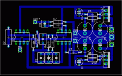
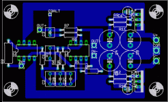
No, it is not a cupper tape, it is some 0.8mm cupper, cut and bend. One leg goes through the pcb to ground.
Coming from this idea: http://www.diyaudio.com/forums/showthread.php?s=&threadid=70378
I cannot answer your question, as I cannot compare it to exactly a same configuration and the amp is not ready yet.
I think, the effect is some shielding and some cooling and maybe therefore stabilizing the circuit a little bit.
But at the ETF 05, Peter Willensward was very convinced about the overall effect of cupper: he is building his amps completely in cupper enclosures.
I had just fun, to make a good looking board, including removing the isolation of the electrolytics. But I was going too far, as I had to replace the 8 bypass Oscon's nearby the chips: they touched the pins 4 and 8
BTW: RJM, did you use successfully the AD797 as input chip?
I had to implement two 20k trimmers, to adjust bias. Otherwise the output bias will already overload the following OPA228.
So, the bias has to be adjusted exactly with my cartridge installed in my TT. The system will absolutely not be portable in this aspect.
Franz
No, it is not a cupper tape, it is some 0.8mm cupper, cut and bend. One leg goes through the pcb to ground.
Coming from this idea: http://www.diyaudio.com/forums/showthread.php?s=&threadid=70378
I cannot answer your question, as I cannot compare it to exactly a same configuration and the amp is not ready yet.
I think, the effect is some shielding and some cooling and maybe therefore stabilizing the circuit a little bit.
But at the ETF 05, Peter Willensward was very convinced about the overall effect of cupper: he is building his amps completely in cupper enclosures.
I had just fun, to make a good looking board, including removing the isolation of the electrolytics. But I was going too far, as I had to replace the 8 bypass Oscon's nearby the chips: they touched the pins 4 and 8

BTW: RJM, did you use successfully the AD797 as input chip?
I had to implement two 20k trimmers, to adjust bias. Otherwise the output bias will already overload the following OPA228.
So, the bias has to be adjusted exactly with my cartridge installed in my TT. The system will absolutely not be portable in this aspect.
Franz
I've been working on the LM317 version of the phonoclone PCB. I'm happy with the arrangement of the regulator components and grounding, but the position of the RIAA components etc is still uncertain along with a number of other things, such as whether its going to be a 'mini' version on the same 1/4 Eurocard size as the VSPS, or whether I'll spread it out in luxury on 1/2 Eurocard as before, with space for larger parts etc., or even if it will be double sided - though I've done it single sided for now.
Feel free to download the source files, above, and play around with it over the new year. See if you can improve on it.
Richard
Feel free to download the source files, above, and play around with it over the new year. See if you can improve on it.
Richard
Attachments
New tests with the ZYX 10 2
Have been playing around with the ZYX and the R1 and R2 values indicated by RJM.
What I like best now is
R1 approx 2R
R2 390R
This together with the 317/337 prereg gives the best so far.
Have to listen more but:
-almost black/no noise background
-fast, crips, musical you name it, awesome
The battery based PSU does not give such a black background, perhaps should try 12 V regulation then.
The gain is still a little high.
I lost the mains humas well
Rerouting + less pick-up due to lower R1 (I think as non electronics engineer)
regards,
E&E
Have been playing around with the ZYX and the R1 and R2 values indicated by RJM.
What I like best now is
R1 approx 2R
R2 390R
This together with the 317/337 prereg gives the best so far.
Have to listen more but:
-almost black/no noise background
-fast, crips, musical you name it, awesome

The battery based PSU does not give such a black background, perhaps should try 12 V regulation then.
The gain is still a little high.
I lost the mains humas well
Rerouting + less pick-up due to lower R1 (I think as non electronics engineer)
regards,
E&E
Speaking from personal experience, stacking boards isn't such a great idea. Nor is trying too hard to stuff everything in a tiny case.
1/8W parts can be used for all resistrors both circuits, as none of the parts draws power above 100mW.
/R
P.S. The new PC board is shaping up to be single sided, VSPS-sized.
1/8W parts can be used for all resistrors both circuits, as none of the parts draws power above 100mW.
/R
P.S. The new PC board is shaping up to be single sided, VSPS-sized.
Attachments
RJM Thanks for the response
The reason I need to stack them is,the phono amps are going into a line amp. The layout space is 10” x 8”,the preamp and power supply takes up half that area. I need room for the pots ,rotary switches and a couple of relays. What if I enclose the lower phono amp in an aluminum case(I have straps of aluminum) and sit the caseless phono amp on top?
The reason I need to stack them is,the phono amps are going into a line amp. The layout space is 10” x 8”,the preamp and power supply takes up half that area. I need room for the pots ,rotary switches and a couple of relays. What if I enclose the lower phono amp in an aluminum case(I have straps of aluminum) and sit the caseless phono amp on top?
When you squeeze everyting into a small space, you've committed then and there on the first try .. no going back and changing anything, 'cause it will get horribly messy and most likely broken if you try. Fine if its your third or fourth Phonoclone, but dicey if its your first. That's all I have against it.
/R
/R
Sorry to be a pest, can I do the same for R7 on the output...?
Its quite a drag trying to lay this out on veroboard strips..., but I think If I get those 2 components off, I might just get it done... currently just laying out with Lochmaster...
PS. don't worry... its starting to get messy, I'll jsut order the ^&$^&$ matrix board from RS, ...AND WAIT YET AGAIN!!!!
Hi Nordic,
Lochmaster is funny.
Here is an old Layout of a Grado PH1 Clone, hope that helps.
Carsten
Lochmaster is funny.
Here is an old Layout of a Grado PH1 Clone, hope that helps.
Carsten
An externally hosted image should be here but it was not working when we last tested it.
Back with the VSPS project, I learnt that the bypass caps should be connected close to the power pins of the op-amp.
BUT
What to do with two op-amps powered by one regulator? Use four bypass caps, two for each op-amp? Or use two bypass caps, reasonably close to both op-amps?
At the moment I've stuck to two bypass caps, to keep to the original 25 parts/channel and because the grounding layout works nicely. With reservations, however. I've tried to migitate against the longish traces by making them as broad as possible and the whole layout as compact as I can.
As I said, nothing set in stone yet.
-rjm
- Home
- Source & Line
- Analogue Source
- The Phonoclone and VSPS PCB Help Desk

