Bonding teflon
Tee- Just wanted to let you know that I bonded a piece of teflon to a piece of aluminum with RTV silicon adhesive. I just spread out a good bead of it to get full contact when clamping it. Now that it has cured, I can't pry it apart. The layer of adhesive is about .015" thick.
The only problem with doing this with your platter is that if you ever want to try a different material, like wood, etc, you would have to machine it off. Also, how does a layer of adhesive afffect resonance??
Colby
Wow Colby - that's really interesting. I never thought RTV would hold to the slippery teflon.
Most of the places I found on the Net that talk about bonding teflon, state that some kind of etching needs to get done to the teflon surface prior to bonding - whether by chemical or physical means.
Anyways - I'm no expert but here's my intuition on the adhesive layer effects on the platter sound FWIW:
Assumption - you would like it not to be there - in the sense that it wont have any audiable effect. However, if it does have an effect, you want it as minimal as possible and as uniform as possible. That's why I believe you want the adhesive layer to be:
a) Thin
b) Uniform
c) Rigid (more or less like the materials it bonds)
I'm sure it affects the overall mechanical response of the platter, but have a gut feeling that if all 3 parameters are kept to sensible levels, it'll be inaudiable or nearly so.
Just a lousy electric engineer's take on mechanical stuff, though - I would ask the experts
-T
RTV
I would not use any compliant material like RTV, within mechanical vibration path, including platter, bearing, base and feet. It affects adversely the sonic signature of the whole assembly. On my splitted platter, I placed once the layer of sorbotane on the bottom side of the upper plate, which was rigidly coupled with the subplatter. Sorbotane sucked the whole life from the music, without even being included directly into vibration path.
I would not use any compliant material like RTV, within mechanical vibration path, including platter, bearing, base and feet. It affects adversely the sonic signature of the whole assembly. On my splitted platter, I placed once the layer of sorbotane on the bottom side of the upper plate, which was rigidly coupled with the subplatter. Sorbotane sucked the whole life from the music, without even being included directly into vibration path.
OK - let me try and answer myself here...

I'm a little worried about the cone stuff. The platter is 2" aluminum topped with 1" teflon. If I get the teflon layer to rest on cones, I'm afraid I'll create more problems than solve ones.
My problem is that the teflon layer is light and not self damping. Now, if the cones were real ideal mechanical diodes connected to a mechanical ground (the self damping aluminum+leadshot subplatter), then I'd be fine. But cones aren't. They are not infinite resistance for vibrations going up since some waves will find their way to the point contact with cone, and more problematically, they are not zero resistance on the way down - waves will travell awhile in the teflon until they find their way to the small cones and then they still need to cope with the impedance difference between the teflon and the cone material. Under these conditions the fact that the teflon layer is light and resonant will likely kill the solution. I think I'll better find a way to fully engage the teflon to the aluminum sub platter and rely on the self damping of the subplatter, bearing, plinth and rack to "ground" the vibration.
I still would like to avoid glueing or bolting. How about stress fit? The aluminum would have multiple small cylindrical protrusions and the teflon will have matching bores, slightly deeper than the protrusions hight to allow full contact of the 2 layers. You lower the teflon onto the aluminum, apply some pressing and viola - the teflon locks in place. Would that work or would the teflon "travell up" with time due to it's slippery characteristics?Maybe a small taper in these joints to create and mechanical lock? Thoughts anyone?
Cheers,
-T
Re: OK - let me try and answer myself here...
Teflon is not a good material to bond, pressfit, and for that matter has terrible "creep" qualities.
I build precision Teflon parts as part of an assembly for NGK America, can't go into details here but I know quite a bit about Teflon. I'd stay away from it, just my opinion.
If you must use it in your application, thread it, and bolt it from the bottom of the aluminum platter and use prestressed bolts and an inch pound torque wrench to bolt it together. Have the machinist bolt it together in a controlled environment (68 degress F) and take a finish cut across the face of the teflon and that's as good as it gets. If you assemble it any other way, no guarantees of flatness over time. Good luck.
Not a good idea. As a machinist speaking here, I see too big a challenge to hold the very close tolerances involved here. It's also a waste of time. Thermal expansion of both materials is very different.Tee-Rex said:
I still would like to avoid glueing or bolting. How about stress fit? The aluminum would have multiple small cylindrical protrusions and the teflon will have matching bores, slightly deeper than the protrusions hight to allow full contact of the 2 layers. You lower the teflon onto the aluminum, apply some pressing and viola - the teflon locks in place. Would that work or would the teflon "travell up" with time due to it's slippery characteristics?Maybe a small taper in these joints to create and mechanical lock? Thoughts anyone?
Cheers,
-T
Teflon is not a good material to bond, pressfit, and for that matter has terrible "creep" qualities.
I build precision Teflon parts as part of an assembly for NGK America, can't go into details here but I know quite a bit about Teflon. I'd stay away from it, just my opinion.
If you must use it in your application, thread it, and bolt it from the bottom of the aluminum platter and use prestressed bolts and an inch pound torque wrench to bolt it together. Have the machinist bolt it together in a controlled environment (68 degress F) and take a finish cut across the face of the teflon and that's as good as it gets. If you assemble it any other way, no guarantees of flatness over time. Good luck.

Platter leadshot damping
Another issue:
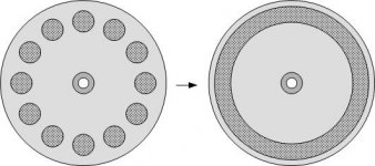
WHY is it that designers damp with 12 (or so) symmetrical circular spaces filled with leadshot. I mean, I'm sure that compromizing the homogenous structure of the platter is not good for the balance - why not keep that to a minimum by constructing 1 concentric "chasm" and fill that with leadshot (make it close to the platter boundary for better inertia). That way, radialy you still have a varying structure, but at least it's tangentially symmetrical. Like in the picture attached.
Anyone?
Thanks
-T
Another issue:
WHY is it that designers damp with 12 (or so) symmetrical circular spaces filled with leadshot. I mean, I'm sure that compromizing the homogenous structure of the platter is not good for the balance - why not keep that to a minimum by constructing 1 concentric "chasm" and fill that with leadshot (make it close to the platter boundary for better inertia). That way, radialy you still have a varying structure, but at least it's tangentially symmetrical. Like in the picture attached.
Anyone?
Thanks
-T
Attachments
Interesting link
Found this link that talks about speed accuracy and vibration control (the topic is the Rockport seriusIII but theres only theoretical discussions in the content).
Pretty basic stuff but very thoroughly analyzed in a very descriptive language. I think it's worth reading.
Here
-T
Found this link that talks about speed accuracy and vibration control (the topic is the Rockport seriusIII but theres only theoretical discussions in the content).
Pretty basic stuff but very thoroughly analyzed in a very descriptive language. I think it's worth reading.
Here
-T
Wow- Long read, but very informative! Made me realize why sometimes I think it sounds like my platter is slowing down. If I don't have the record clamped tight, I think it might be slipping on the teflon. I have to have it clamped just to brush the record! Another drawback to teflon. I think I might need to have a go at some other material for the top layer.
I thought about this and decided to keep posting thoughts - although not always getting answers/comments. It's OK - it may be boring to people, but it helps me think straight. So, here goes:
The link above got me thinking about vibrations in the tangential direction and the idea of separating top platter from sub platter with cones. The sub platter (2" alu) is heavy and self damping (high enertia, leadshot, bearing oil viscosity etc.). The top platter (1" PVC for the time being) is rather light with little or no self damping ability. I'm assuming a few things to be ideal for the sake of this analysis:
1) Vertical vibrations are handled by the cones acting as mechanical diodes. Hence, I will only analyze horizontal movement, and specifically tangential one, which is actually the vector element being translated as effecting speed stability
2) I'll assume that the bottom platter has an infinite ability to damp stylus induced vibrations. However, it's still causing it's own vibrations.
3) Top platter and record are regarded as one mechanical unit.
Now the target is twofold - vibrations coming from the stylus should be fully transmitted down to the sub platter where they would be mechanically "grounded". But vibrations from the sub-platter (coming from motor, belt, bearing etc.) should not travel up to the top platter-record-stylus. After giving that some thought, I've come to think it's impossible. That is because, as Einstein noticed, there is no difference between top platter moving wrt the sub-platter and the sub-platter moving wrt top platter. That was a discomforting thought, but then I realised something else. There is a difference between the 2 types of vibrations (and remember we're talking tangential direction only). While forces coming from the sub-platter have all the reasons to statistically of the same amplitude to both sides (that is, want to slow and speed up the record at the same level when averaged), stylus induced forces are only in one direction. That is, there is the force the stylus exerts when meeting a loud passage in the groove that wants to slow down the turning of the record, but coming out of the slope in the vinyl, it won’t really try to "push" the record to go faster. Thus the stylus only creates a drag force, an a-symmetrical one, and assuming the sub-platter applied forces are symmetrical, it's safe to assume that the average composite vector applied to the interface between the 2 platter parts is not zero, but is actually a vector that wants to slow down the platter.
I think that it would be beneficial in that case to make the interface between the platters a-symmetrical in a way that makes the system reject dragging forces more than it rejects speeding forces. The balance point between tradeoffs can be optimized.
So I attached 4 diagrams. They show the record spinning and the stylus hitting a loud passage. The blue arrows show the forces working – sub-platter forces going both directions and stylus forces going one way. The red arrows, OTOH, show the vibrations in the top platter (and hence the record) resulting from these forces given the different damping abilities of the different system parts. Figure (a) shows what happens if the platters are tightly coupled (bolted or glued). Given the assumptions I described above, 100% of the sub-platter induced forces will translate to vibrations in the top platter, where as the stylus induced forces are TOTALLY damped by the full coupling to the damping sub-platter. Figure (b) shows the top platter resting on cones, residing inside spherical bores in the sub platter. Any horizontal movement of one platter wrt the other is somewhat damped by the cones needing to travel up the spherical slope, thus working against gravity. That’s why the red arrows are slightly shorter than the blue ones.
Figure (c) takes advantage of the knowledge that there is more drag than push force – one side of the bore is completely coupled to the cone – totally preventing stylus dragging by transmitting all of it to the damping sub platter. On the other hand, subplatter induced forces in this direction will also be fully transmitted upwards with zero damping. The opposite side of the bore is as spherical as in figure (b), allowing the same partial damping for vibrations in that direction coming up from the sub platter to the top platter, and compromising nothing in terms of transmitting downwards going vibrations, as these are non existent in this direction.
Figure (d) is a compromise between the (b) and (c). Both sides of the bore are spherical – but the one that needs to damp down-going stylus drag forces has a noticeably stronger slope presenting more damping in this direction than the milder slope on the other side dealing only with sub-platter induced forces.
I think solutions c & d are better than a & b – but not sure. Also I don’t know how machinable this is. Now if anyone had enough patience to go through this tiresome explanation – I’d appreciate your views.
Thanks
-T
Attachments
Tried to read that thesis on motors - lots of impresive words but I'm sure I think it all correct - way to verbose for me to wade through especially since I'm not making a turntable.
One example: not all motors do the kick and coast thing - for example a stepper motor driven by a quadrature sine waves (90° phase) has constant drive - this effect is used to do micro stepping. Then the worry is how perfect is the machining - ie are all the steps equal.
I also do not agree with the premise that the cartridge is responsible for the amplitude - the platter, plinth do not vibrate???? put the stylus down on a turning record and listen to plinth using a screw driver as a stethascope (spelling?) - And the turntable responsible for all the timing, is the cartridge perfectly stiff in the lateral (with the groove), that is it does not move at all (this is probably nearly true). The article talks about the cartridge effecting the speed - do different cartridges behave differently?
Anyway I did not have patience to plow through all that stuff - some is probably good - just easier to think about myself, which means that maybe I'll miss the pearl of wisdom in there!
Bill
For some unusual ideas on tt design study the Well Tempered Turntable - I like many of its features and the bearing design would be easy to DIY. Oh and ignore the Stereofile comment that it lacks a suspension - it does not - it does not have a bouncy one but that is a feature! - I believe that long article mentions some of the speed problems that can arise from motor and platter moving relative to one another.
I'm biased, I own one - put together from various bits left over from customers upgrading many years ago and a few new bits, and some custom pieces. Some day I'll make that custom motor supply I designed so many years ago.
- Status
- This old topic is closed. If you want to reopen this topic, contact a moderator using the "Report Post" button.
- Home
- Source & Line
- Analogue Source
- DIY TT design