thanks guys
the whole idea was a DIY dream ...made for you
everything is there for you to play with ...and its real fun playing with the results
and now over the last months i have let a few peeps compare my floppy deck with its new linn inner and outer platter ...to a standard lp12
half prefer the the floppy and half the lp12...and me im happy with both...") #
#
there was a small typo in the wirein section in my floppy web page its been sorted now (hrrmm just incase any1 had problems)
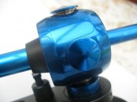
its fitted with this arm at the moment
best wishes for now
j7
the whole idea was a DIY dream ...made for you
everything is there for you to play with ...and its real fun playing with the results
and now over the last months i have let a few peeps compare my floppy deck with its new linn inner and outer platter ...to a standard lp12
half prefer the the floppy and half the lp12...and me im happy with both...
#there was a small typo in the wirein section in my floppy web page its been sorted now (hrrmm just incase any1 had problems)
its fitted with this arm at the moment
best wishes for now
j7
Attachments
Oscillator Question
I am trying to contact Ouroboros specifically. Since I just signed up to the forum I cannot send e-mails. I am very new to electronics and have some very basic questions about the three-phase oscillator. As in, where should I hook up the battery, what kind of zener diode could I replace the surface mount with (would a 1N4733 work?). When I get it up and running, do I need to play with the resistance of all the resistors in order to adjust the speed or would a pot on r3 or r2 suffice? Also what are the zener diodes for?
Thank you,
Yann
The schematic I showed was from my SPICE simulation. In the real world you'll have to run the op-amps from symetrical +/- supplies, (I am running from +/-12V rails). You could run off a single supply if you provide a mid-rail reference for the op-amps to connect to where the ground symbols are shown on the schematic I posted. You'll need to look at some of the design resources on the web if you're not too sure how to do this.
The series back-to-back Zeners are to apply a non-linear gain reduction in the first op-amp to limit the pk-pk output. If they were not there the op-amps output would increase to clipping, giving a very distorted waveform.
To change the frequency, you really need to change the value of all three 10k resistors together, but if all you wanted to do was slightly tweak the output frequency by a few percent then you might get away with changing the value of just one of them.
Have you considered doing this digitally instead? You can generate a 3-phase sine-wave by making a 12-bit 'twisted-tail ring counter' and having resistive summing networks attached to the Q outputs of each stage. Basically you produce a stepped approximation to a sine wave which can be filtered using a simple first-order R-C network. Let me know if you want me to sketch out the basic circuit.
There's an easy way to generate three phases out of a two phase supply by vector summation.
If you have 0 and 90 degrees you can make any other angle using a summing amplifier. As an example, -0.5 x 0 + .866 x 90 = 120 and -0.5 x 0 + -.866 x 90 = 240. Note that the easiest summing amplifiers invert so the second sum is easier than the first. This difficulty is solved by using an inverting amplifier before the summing amplifier.
BTW these sorts of arithmetical operations were the original raison d'etre (and the source of the name) of the op-amp
- Status
- This old topic is closed. If you want to reopen this topic, contact a moderator using the "Report Post" button.