Designing a decent RIAA phono preamp actually requires some
reasonable amount of analog design skill. The combination
of signal levels, source impedances, RIAA EQ curve, etc.
require the careful tradeoff of conflicting requirements.
You just don't run out and randomly grab a few passive
components and your DIY audiophile op-amp-du-jour and
throw together a decent circuit.
Brian! this I am fully aware of , however I cannot see the guys at national semi conductor knowingly publishing dud information ! can you ! and if you take a bit of time to reacd my post I was comparing this circuit too:> "the one op amp types` normally found in most mixers,integrated amps " !!!!!!!
Besides this even the best theoretically designed circuits are only as good as their implementation (signal capacitors ,psu quality board layout etc.etc.) which is roughly what we are talking about here. Not that I am saying these make a silk purse out of a sow`s ear but get these wong with a decent curcuit and it will let you know
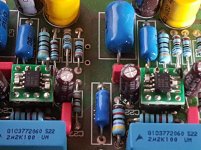
evengravy said:love the design layout, beautifull, could you tell me what type of cap you used (the blue types that look like mustard caps)
Thanks! The blue caps are Philips/BC polypropylene film/foil caps. They are available in all E-24 values, so they are often used for RIAA filters
")
Best regards,
Mikkel C. Simonsen
djaleksei said:Could somebody tell me where can I order hi quality parts in the US? Any online store out there? I live in a very small town near United States so here I can't buy nothing but standard caps, resistors, and ICs... I'd like to know where to get 1% resistors and hi quality caps on the net! Thanks.
IIRC, Newark has no minimums on most products or minimum $$$ amount without a surcharge!
http://www.newark.com/
Regards//KP
Ref post #22, MCS RIAA-kit:
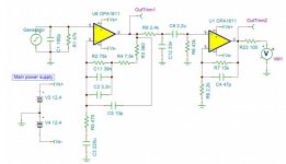
With professional help from a reputated audio engineer, the MCA-kit is adjusted and stabilized for today's opamp OPA 1611.
The onboard AC/DC and regulators was noisy and replaced by an outboard power supply and Jung regulator.
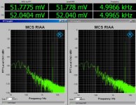
The deviations on the right and left channels from the standard RIAA curve are -0.3dB at 20Hz, + 0.2dB at 200Hz, otherwise almost within 0.1dB.
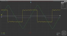
The deviations between the channels are only 0.04dB and must say to be very good. The square pulse beneath is 20 khz. Before you ask: I can't answer...
With professional help from a reputated audio engineer, the MCA-kit is adjusted and stabilized for today's opamp OPA 1611.
The onboard AC/DC and regulators was noisy and replaced by an outboard power supply and Jung regulator.
The deviations on the right and left channels from the standard RIAA curve are -0.3dB at 20Hz, + 0.2dB at 200Hz, otherwise almost within 0.1dB.
The deviations between the channels are only 0.04dB and must say to be very good. The square pulse beneath is 20 khz. Before you ask: I can't answer...
Attachments
Mentioned early in this thread, but still by far the best phono preamp for the $$ is Rod Elliott's: Hi-Fi RIAA Phono Preamp
and, even better yet, the low-noise version (~3db quieter) available if you buy his circuit board.
and, even better yet, the low-noise version (~3db quieter) available if you buy his circuit board.
Ref post #22, MCS RIAA-kit:
With professional help from a reputated audio engineer, the MCA-kit is adjusted and stabilized for today's opamp OPA 1611.
The onboard AC/DC and regulators was noisy and replaced by an outboard power supply and Jung regulator.
The deviations on the right and left channels from the standard RIAA curve are -0.3dB at 20Hz, + 0.2dB at 200Hz, otherwise almost within 0.1dB.
The deviations between the channels are only 0.04dB and must say to be very good. The square pulse beneath is 20 khz. Before you ask: I can't answer...
Kind of answer:
This circuit is meant for use with MM or high output MC cartridges.
Input resistance and capacitance can be tailored by replacing C1/R1 (and the other channel C4/R10) to desired values.
Last edited:
Hey folks...
I am building a phono preamp for my daughter & son-in-law. They are not going to be too discriminating, but I might as well put some effort into it.
I bought a PCB from someone on e-Bay, based on the NSC AN-346 2-stage RIAA preamp circuit. This uses 39 nF and 33 nF in the time constant circuits and a 2 uF coupling capacitor.
I forgot how hard it is to find capacitors that meet desired capacitance, dielectric, construction, lead pitch, and tolerance.
I ordered 60 each MKP-type 5% tolerance inexpensively (double-metallized, just because I found those values with desired lead pitch for PCB). I have access to a calibrated metrology lab standard RLC 'meter' with several digit display and will number them all and bin them by value to match values (hoping they aren't all hovering close to the 5% extreme - found that phenomenon once trying to select Zener diodes for a low-end-of-tolerance value, and they all were extremely close to each other with not enough variation to chose values close enough to what the situation needed).
So I began contemplating how sensitive the RIAA time constants might be to tolerance, thought I understood what I was doing...
...until I read a paper today on evolution of the RIAA EQ. from 2 to 3 to 4 time constants. It analyzed the sensitivity of each time constant with regard to interaction among the 4 time constants. It concluded that the 4th time constant had the worst sensitivity to components, most people advise avoiding implementation of the 4th time constant, and that the ratio of the capacitors for the two 'conventional' time constants is very important.
Back to the NSC App. Note. It derives equations and allows choice of the capacitors. No discussion of capacitor ratio. Different circuit, I suppose.
I'm a little disturbed I read the paper with the critical ratio capacitors, as the AN-346 one is only a little bit of work to recalculate component values based on one's choices.
I am glad to see an included schematic posted here with '1611 op amps that, while it differs from AN-346, I recognize some similarity and it DOES use the same 39 and 33 nF values I decided to find.
The only disappointing thing about the AN-346 2-stage is the 200 uF BP electrolytic, but a film cap in that value, while available now, is impractically huge.
I know where my NE5534A's are but don't remember where (too much stuff in boxes) my modern op amps are, so I'll use what I have accessible.
Any opinions on the two different philosophies (or context I missed) of critical ratio of two capacitors vs. chose desired values? (I almost decided to recalculate for equal value capacitors since I have a lot of certain values in polystyrene).
Thanks for reading and your thoughts.
Murray
I found some ancient NOS Sprague 96P Vitamin Q 0.039 and 0.033 uF but cannot bring myself to use those with op amps...for various reasons, mainly the common opinion they need 50-100 hours of use to sound 'good'. To build a preamp for someone who doesn't understand this seems a really bad idea...MKP type will hit the ground running and if they change with burn-in, it will be subtle.
For C1 suggest
594-222241643903
MKP416 0.039 uF 2 %
You could use it for C3 as well but if you do R3 has to change
594-222241643903
MKP416 0.039 uF 2 %
You could use it for C3 as well but if you do R3 has to change
Then DC servo the circuit and remove the big FB cap.The only disappointing thing about the AN-346 2-stage is the 200 uF BP electrolytic, but a film cap in that value, while available now, is impractically huge.
If you're going opamp, go with this schematic:
http://www.hagtech.com/pdf/bugle3.pdf
I can confirm it works well. Once you have 1 opamp, you might as well continue using them. LM4562 = LME49720: Same exact chip, one might be more available than the other.
http://www.hagtech.com/pdf/bugle3.pdf
I can confirm it works well. Once you have 1 opamp, you might as well continue using them. LM4562 = LME49720: Same exact chip, one might be more available than the other.
I know where my NE5534A's are but don't remember where (too much stuff in boxes) my modern op amps are, so I'll use what I have accessible.
Go for it.
Those 5534 will sound stellar.
After rolling a lot of opamps, I came back to these old beans.
Using them on an RJM VSPS with beefed up PSU.
Basically the PSU part of Lehmann BCL I had laying around.
Omitted the output caps altogether since my next stage is AC coupled.
Polysterene RIAA caps and for decoupling.
Will try some silver MICA there soon.
Metal fimls are used for the RIAA.
I use new carbon composition resistors for loading and for the output resistors. They add some tubiness to the mix.
Nobody's drooling over KEMET R76 MKP type in the audio crowd, but I am absolutely impressed with their reliability in theory and industrial applications.
I enjoy the sound of the axial MKP from Kemet (Arcotronics).
Also, the PME series of metallised paper (up to 1uF i think) are quite nice.
If those are Philips/Signetics NE5534As, I'd very much like to purchase them from you if you are not going to use them in your project. PM me if you's be willing to sell them.I know where my NE5534A's are but don't remember where (too much stuff in boxes) my modern op amps are, so I'll use what I have accessible.
Here is the schematic, published by Hagerman Labs, for their 'Bugle3' op-amp phono stage which was mentioned somewhere upthread. As a bonus, the second document shows the schematic for their discrete FET 'Piccolo2' headamp. I really like both circuits.
http://www.hagtech.com/pdf/bugle3.pdf
http://www.hagtech.com/pdf/piccolo2.pdf
http://www.hagtech.com/pdf/bugle3.pdf
http://www.hagtech.com/pdf/piccolo2.pdf
I f you are going to lock yourself in to an OPAMP based design, would strongly urge you to check out Sparkos labs. He builds discrete opamps that plug into a standard socket, and sound so much better than any Integrated circuit chip....
Sparkos Labs, Inc. High End audio components and Hi Fi Audio Gear.
Sparkos Labs, Inc. High End audio components and Hi Fi Audio Gear.
- Status
- This old topic is closed. If you want to reopen this topic, contact a moderator using the "Report Post" button.
- Home
- Source & Line
- Analogue Source
- The best phono preamp on op-amps?