It was brought to my attention recently that the 47 Labs Phonocube uses an OP27G as the front end op-amp.
I'd always held out for the AD797, but although the OP27 is has about five times the voltage noise, its low bandwidth and slow slew rate would make it a much easier beast to implement.
It seems that every few months something comes up regarding this project that has me scribbling out layouts at all hours of the day. So it is that I've come up with a new layout for the phonoclone that has separate voltage regulation for the input and output op-amps. It has the requisite 25 parts per channel and I'm confident that its pretty close to the Phonocube design. The layout, however, still looks too complex to be a good match.
More info :
http://www.geocities.com/rjm003.geo/rjmaudio/diy_pho4.html
Attachments
OP27 output stages
Shown in the attached image is the output sections for the Analog Devices OP27, the TI OP27 and the LT1007.
The LT1007 appears to be a different, but I'm curious about the two OP27s. The TI schematic shows two pnp transistors for the output Q45,46, while the AD schematic shows a complimentary pnp, npn set.
I'm quite ignorant of transistor circuits. Are the two OP27 schematics equivalent? Is one a typo? If the schematics are correct, given the choice is one arrangement preferable to the other?
thanks
-rjm
Attachments
Re: OP27 output stages
Hey that's funny the TI OP27 is using all NPN transistors. (Not PNP as you wrote erroneously)
First time I see a second sourced part with a different simplified schematic.

Hi rjm,rjm said:Shown in the attached image is the output sections for the Analog Devices OP27, the TI OP27 and the LT1007.
The LT1007 appears to be a different, but I'm curious about the two OP27s. The TI schematic shows two pnp transistors for the output Q45,46, while the AD schematic shows a complimentary pnp, npn set.
I'm quite ignorant of transistor circuits. Are the two OP27 schematics equivalent? Is one a typo? If the schematics are correct, given the choice is one arrangement preferable to the other?
thanks
-rjm
Hey that's funny the TI OP27 is using all NPN transistors. (Not PNP as you wrote erroneously)
First time I see a second sourced part with a different simplified schematic.
Another Layout
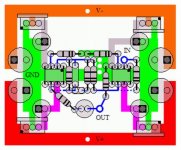
Here's another layout. Its the same circuit as above, but with a simpler arrangement. The power rails are now on the outside, with the regulator and bypass caps on the four corners. The signal grounds all connect to the central bulge of the ground tab.
-rjm
Here's another layout. Its the same circuit as above, but with a simpler arrangement. The power rails are now on the outside, with the regulator and bypass caps on the four corners. The signal grounds all connect to the central bulge of the ground tab.
-rjm
Attachments
and lastly (for now)
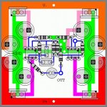
- Expanded to square shape.
- Narrowed the center ground trace, so the signal runs under the IC. This removed the need to bridge over traces, everything is now a simple single sided layout.
- Added a little more room for larger capacitors.
-rjm
- Expanded to square shape.
- Narrowed the center ground trace, so the signal runs under the IC. This removed the need to bridge over traces, everything is now a simple single sided layout.
- Added a little more room for larger capacitors.
-rjm
Attachments
Re: and lastly (for now)
Just had a look at the layout and this design uses two single opamps per channel and you have 2 regs per opamp = 8 regs for one stereo phonoclone!
So maybe you should separate the psu section so we can only use 2 regs for all opamps? just a thought
rjm said:- Expanded to square shape.
- Narrowed the center ground trace, so the signal runs under the IC. This removed the need to bridge over traces, everything is now a simple single sided layout.
- Added a little more room for larger capacitors.
-rjm
Just had a look at the layout and this design uses two single opamps per channel and you have 2 regs per opamp = 8 regs for one stereo phonoclone!
So maybe you should separate the psu section so we can only use 2 regs for all opamps? just a thought
Re: Re: and lastly (for now)
One of the tricks to get the most out of opamps is to use lots & lots of regs.
dave
maxw said:Just had a look at the layout and this design uses two single opamps per channel and you have 2 regs per opamp = 8 regs for one stereo phonoclone!
So maybe you should separate the psu section so we can only use 2 regs for all opamps? just a thought
One of the tricks to get the most out of opamps is to use lots & lots of regs.
dave
Phonoclone Circuit
It on the web page, but for easy reference I'll copy it to this thread.
Parts list for one channel:
R1 47R (Denon DL103, set equal to cartridge impedance)
R2 6k8 (Denon DL103, 75dB gain, calculate for desired cartridge/gain)
R3 680R
R4 680R
R5 33k *
R6 220k *
R7 33k
R8 47R
C1 3.3 nF (WIMA MKP) *
C2 10 nF (WIMA MKP) *
C3 4.7 µF (Black Gate non-polar)
U1 (OP27 for 75dB)
(OP37 for 90dB)
U2 OP27 ?
* RIAA values, match to 1%.
also needed, 2 each LM78xx and LM79xx regulators, and eight low-impedance filter capacitors, 47-220 µF .
and the appropriate power supply
Attachments
maxw:
People who've spent the money on a low-output moving coil cartridge to use with the Phonoclone probably won't get too worried at the prospect of 8 voltage regulators. In this instance I think they should be considered a necessary part of the amplifier circuit, rather than an optional part of the power supply.
However if you want to, for example, use a battery power supply, or just for the hell of it, attached is what it would look like sans regulators.
-rjm
Attachments
Hi RJM,
A few questions for you:
1) Has this project now left the "Early development stage"?
2) Are there any dual opamps that meet the specs, one per channel could reduce the signal path and amound of components.
3) How does it perform with the Dl103 compared to a high gain VSPS?
A few questions for you:
1) Has this project now left the "Early development stage"?
2) Are there any dual opamps that meet the specs, one per channel could reduce the signal path and amound of components.
3) How does it perform with the Dl103 compared to a high gain VSPS?
Questioning...
I wonder if the 47 ohm on the inverting input is correct?
In your design it is set to match the DL103 impedance on the non inverting input. But the original design says i't more or less independant of the carts impedance. It also says that input impedance is 0 zero!. Because an MC cart is a balanced source, putting a load only at the - pole seems not correct because it still means there is a load impedance!
Because it is MC only would't it be possible that the - pole is separated from ground and the aproach treats the balanced signal of the MC cart also that way.
Prject Status
I've been sitting on this project for more than two years. What happened was I got 80% of the way there but then took a wrong turn trying to fit the AD797 into the 25 part scheme of things. Learning about the OP27 let me settle on the 4 regulators in place of the various bypass and decompensation caps needed for the AD797. Than, in turn, got me thinking about the layout again and finally I managed to come up with something that was small, simple and correct in terms of the grounding scheme.
The Phonoclone has been next on my "build list" since finishing the MC step up transformers six months ago. But... its going to be 2-3 more months before I'm likely to finish. Audio projects have a way of disappearing off the horizon for weeks at a time for various reasons. So I can't answer "how does it sound" questions. Reviews of the Phonocube can give you some idea of what we are aiming for. The VSPS was actually conceived as a proof-of-concept of the Phonoclone's RIAA circuit and power supply, and I built that, so the circuit has been partially tested at least.
Regarding the choice of op-amp. The input offset voltage of the OPA627AP is typically 300�@uV, roughly ten times that of the OP27. This limits the OPA627 to the low gain configuration, but it is otherwise suitable.
Since a dual opamp by definition shares the power supply you can't build a Phonoclone with dual opamps. You can build something similar, I suppose, with a reworked layout, but I'm not sure offhand what would be a suitable IC to use. Actually since the signal path is already only the length of the components, you wouldn't gain anything in that respect by moving to a dual IC.
Lastly for Eric, the short answer to your question "I wonder if the 47 ohm on the [non]inverting input is correct?" is "yes, I believe it is... since the cartridge coil is connected to the circuit ground the full output signal, and the full output impedance, is seen at the end of the coil that is connected to the amplifier's inverting terminal." You some potentially interesting points, but please edit your question replacing "inverted" with "non-inverted" and "+" with "-" in all the right places first.
-rjm
PS. the PCB is now down to 2 inches square! The feedback resistor of the first stage is, a la gainclone, soldered across the opamp terminals.
Attachments
There is nothing new about using an IC opamp in the inverting configuration as a current amplifier.
The best article I've ever read about it was written by Stan Curtis and published in the December 1981 issue of Hi-Fi News & Record Review.
He explains the logic of using shunt feedback with NO cartridge loading resistor.
The best article I've ever read about it was written by Stan Curtis and published in the December 1981 issue of Hi-Fi News & Record Review.
He explains the logic of using shunt feedback with NO cartridge loading resistor.
If you dig the forum for other posts you will eventually get into a vicious circle and end up with other threads from Richard. (With interesting information by the way)
I notice that starting in 1974 various designs with similar approach have been used for MC pre's. Apparantly they did not sound good until the Dynavector design and even more the 47labs design.
Now my guess is there are 2 basic diferences between the "old" and "new" designs that are the reason for the quality improvement.
1) the quality of the used components has improved a lot.
2) The general approach to built a good power supply for the designs has changed a lot.
Power Supply question
I'm just curious - trying to get my learn on
RJM - why does your PSU have such a small amount of capacitance? In comparing your design to one found on TNT
http://www.tnt-audio.com/clinica/solidphono_e.html this one uses a hugh amount of capacitance...
why such a difference?
thanks
Brett
I'm just curious - trying to get my learn on
RJM - why does your PSU have such a small amount of capacitance? In comparing your design to one found on TNT
http://www.tnt-audio.com/clinica/solidphono_e.html this one uses a hugh amount of capacitance...
why such a difference?
thanks
Brett
Filter capacitance.
Its a matter of personal taste. You can add as much as you like.
For the same reason the Gaincard/Gainclone only uses 1000uF per rail per channel, I choose to use the "minimum sufficient" capacitance for the phono circuit as well. I rely on the power supply transformer rather than the capacitor to keep the supply rail solid over transients.
Technically, the absolute minimum capcitance is such that the ripple never causes dropouts on the voltage regulator under any circumstances. In practice for opamps, which draw essentially no current, a few hundred uF is more than enough.
Reviewing the VSPS, since four opamps are powered from one filter cap per rail, going to 470uF here would be appropriate. The Phonoclone, however, which has a separate filter cap for each opamp, 100uF should be about right. I havent decided what Ill try first but 100uF before and 47uF after looks good, or maybe Ill double check the ripple voltages and see if I can get away with 47uF in and out.
-rjm
- Status
- This old topic is closed. If you want to reopen this topic, contact a moderator using the "Report Post" button.
- Home
- Source & Line
- Analogue Source
- Phonoclone Update