I have had a play in eagle.
I have not added holes for v+, GND etc yet, and I am not sure on the size of any of the caps lead spacing.
What do you think as far as component placement?
Im sure there is a better way to lay it out but I haven't worked it out yet
I have not added holes for v+, GND etc yet, and I am not sure on the size of any of the caps lead spacing.
What do you think as far as component placement?
Im sure there is a better way to lay it out but I haven't worked it out yet
Attachments
I dig it.
For the supply caps, figure 0.3" lead spacing, 0.4" dia. max. The 4.7uF black gate coupling cap is also axial electrolytic, 0.2" dia. and 0.1" lead spacing.
You need to add a little more room for the output coupling cap, and some more space too for the wire leads to attach.
-rjm
For the supply caps, figure 0.3" lead spacing, 0.4" dia. max. The 4.7uF black gate coupling cap is also axial electrolytic, 0.2" dia. and 0.1" lead spacing.
You need to add a little more room for the output coupling cap, and some more space too for the wire leads to attach.
-rjm
I have followed the development of this Phonoclone with interest for some time.
Anyway, the Phonoclone is made for the DL-103. My question is, what would have to be changed if I was to use an SPU? I ask also because the design seems simple enough for me to actually learn something. And that can't be bad.
Anyway, the Phonoclone is made for the DL-103. My question is, what would have to be changed if I was to use an SPU? I ask also because the design seems simple enough for me to actually learn something. And that can't be bad.
Hi Maxw,
Correction: the power supply caps should be 0.2" spacing, 0.3" dia max. I'm about half way through building the first prototype on veroboard. With luck I should be finished in a week...
I'm pretty stoked to see how my prototype will sound. I'm using a VSPS with Tamura step up transformers right now, with an all-Denon front end: DP-2000 deck, DA-307 arm, and DL-103 cart, and I gotta say its one sweet combo. So it'll be a fair fight, so to speak.
meanwhile, phn,
Although I listed the components for the DL103 since that's what I'll be using, you only need to change one resistor (R2) to set the gain to work with your particular setup. Try to avoid choosing values below 1k, so as not to overload the output of the first stage.
The Ortofon SPU has a sensitivity of 0.2 mV, and an internal resistance 1.5ohm. I recommend you settle for the 90dB side of the gain equation, and go with R2 = 1.5k.
I'd also suggest you try removing R1 and connecting the noninverting input directly to ground instead.
-rjm
Correction: the power supply caps should be 0.2" spacing, 0.3" dia max. I'm about half way through building the first prototype on veroboard. With luck I should be finished in a week...
I'm pretty stoked to see how my prototype will sound. I'm using a VSPS with Tamura step up transformers right now, with an all-Denon front end: DP-2000 deck, DA-307 arm, and DL-103 cart, and I gotta say its one sweet combo. So it'll be a fair fight, so to speak.
meanwhile, phn,
phn said:My question is, what would have to be changed if I was to use an SPU?
Although I listed the components for the DL103 since that's what I'll be using, you only need to change one resistor (R2) to set the gain to work with your particular setup. Try to avoid choosing values below 1k, so as not to overload the output of the first stage.
The Ortofon SPU has a sensitivity of 0.2 mV, and an internal resistance 1.5ohm. I recommend you settle for the 90dB side of the gain equation, and go with R2 = 1.5k.
I'd also suggest you try removing R1 and connecting the noninverting input directly to ground instead.
-rjm
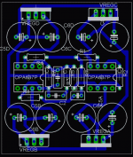
Nice work, maxw -
Thinking on my prototype, 0.3" spacing you have for the resistors is a bit tight for standard 1/4w types. It can be done... but 0.4" leaves the leads in a more natural position.
Likewise the RIAA caps are PCM 7.5, or 0.3" ... it looks like you have them set at 0.2".
There's a orphan through-hole near C5A, center right.
Last, I was wondering what would happen if you turned all the regulators in on themselves, rotating the four blocks of capacitor-regulator-capacitor by 90 degrees. Seems to me the traces for the power supply parts could be shortened that way.
-rjm
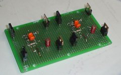
P.S. I am downloading Eagle as we speak, but it may take me a while to learn enough to be able to do anything useful with it...
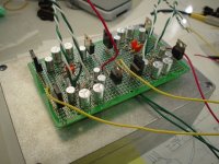
P.P.S. Attached is the phonoclone prototype as it looks now, unfinished. Missing still are the power supply caps and connections. The sockets and most of the resistors are on the flip side.
Thinking on my prototype, 0.3" spacing you have for the resistors is a bit tight for standard 1/4w types. It can be done... but 0.4" leaves the leads in a more natural position.
Likewise the RIAA caps are PCM 7.5, or 0.3" ... it looks like you have them set at 0.2".
There's a orphan through-hole near C5A, center right.
Last, I was wondering what would happen if you turned all the regulators in on themselves, rotating the four blocks of capacitor-regulator-capacitor by 90 degrees. Seems to me the traces for the power supply parts could be shortened that way.
-rjm
P.S. I am downloading Eagle as we speak, but it may take me a while to learn enough to be able to do anything useful with it...
P.P.S. Attached is the phonoclone prototype as it looks now, unfinished. Missing still are the power supply caps and connections. The sockets and most of the resistors are on the flip side.
Attachments
Thanks for the reply. Unfortunately, it didn't make me as wise as I hoped. My thinking was that if I knew the values of the DL-103 and SPU, I should be able to figure the values out for other carts, like the EMT. But you tell me to change the value from 68k to 1.5k. That is 68k for a cart with an internal resistance of 40 ohms and 1.5k for 1.5 ohms (actually 2 ohms according to the Ortofon site). That should place the EMT, with 22 ohms impedance and 1 mV output, somewhere in between. But with the high output I guess there may be other changes in place.
"Noninverting" throws me here. Unless you mean to just skip the R1 and connect the U1 directly to the ground.
I also would like to thank maxw. His work will come in handy should I decide to go about with this. (I'm still scouting the alternatives out there.) I don't have a CAD program to open the Eagle file. (I assume it's some sort of CAD file.) But when time comes, I can probably download some trail version.
I'd also suggest you try removing R1 and connecting the noninverting input directly to ground instead.
"Noninverting" throws me here. Unless you mean to just skip the R1 and connect the U1 directly to the ground.
I also would like to thank maxw. His work will come in handy should I decide to go about with this. (I'm still scouting the alternatives out there.) I don't have a CAD program to open the Eagle file. (I assume it's some sort of CAD file.) But when time comes, I can probably download some trail version.
phn said:ThanksI also would like to thank maxw. His work will come in handy should I decide to go about with this. (I'm still scouting the alternatives out there.) I don't have a CAD program to open the Eagle file. (I assume it's some sort of CAD file.) But when time comes, I can probably download some trail version.
Its nice to be able to do at least something for a community that has given me so much

If you need a link then here is where you go to download eagle:
http://www.cadsoft.de/download.htm
Good luck with your project phn, sorry I cant help you more!
Phonoclone Gain
Sorry for any confusion. R2 is 6.8k (aka 6k8) for a DL103, not 68k. That gives 75dB gain.
If your Ortofon is 2 ohms, that's 20 times less than the DL103, so for the same gain R2 would be 340 ohms. As you expected, its just a linear relationship. The problem here is the combined load of the first stage [(R2+Zcart)||R3] works out to only 220 ohms, a little low for the opamp. Increasing R2 increases the gain, as follows:
Total Gain= 30 + 20log(R2/Zcart) in dB
or
30 x R2 / Zcart, as a multiple
For a 2V output (line level), about 75dB is needed for a 0.4 mV cartridge. For 0.2mV, that's about 80dB.
So the problem is the Ortofon has a rather high output for such a low internal resistance. You either have to load the opamp, or suffer from a higher than line-level output. Looking at it again I'd suggest 680 ohms rather than 1.5k for R2, risking a little loading to obtain a true line-level output.
When I suggested removing R1, I should probably have said "short the non-inverting input to ground". Likewise I forgot to mention that with high gain versions (above 80dB) the OP37 is a better choice than the OP27 due to bandwidth concerns.
Hope that helps...
-rjm
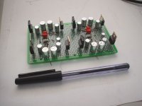
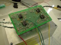
P.S. The prototype board is finished, complete with leads.
Sorry for any confusion. R2 is 6.8k (aka 6k8) for a DL103, not 68k. That gives 75dB gain.
If your Ortofon is 2 ohms, that's 20 times less than the DL103, so for the same gain R2 would be 340 ohms. As you expected, its just a linear relationship. The problem here is the combined load of the first stage [(R2+Zcart)||R3] works out to only 220 ohms, a little low for the opamp. Increasing R2 increases the gain, as follows:
Total Gain= 30 + 20log(R2/Zcart) in dB
or
30 x R2 / Zcart, as a multiple
For a 2V output (line level), about 75dB is needed for a 0.4 mV cartridge. For 0.2mV, that's about 80dB.
So the problem is the Ortofon has a rather high output for such a low internal resistance. You either have to load the opamp, or suffer from a higher than line-level output. Looking at it again I'd suggest 680 ohms rather than 1.5k for R2, risking a little loading to obtain a true line-level output.
When I suggested removing R1, I should probably have said "short the non-inverting input to ground". Likewise I forgot to mention that with high gain versions (above 80dB) the OP37 is a better choice than the OP27 due to bandwidth concerns.
Hope that helps...
-rjm
P.S. The prototype board is finished, complete with leads.
Attachments
6-point-8. Of course. I guess it was just figures for me when I wrote it. 6.8^whatever.
I don't think there's any problem with your explanations. It's just that this lingo is all new to me. And it's not like I will learn most of it. That's for you tech heads. I mean that respectfully. I realize what you do take competence and effort. I don't have the former and can't afford to put in the latter. I remember the "log" from my high school math, but I don't remember what it is. I don't even think I could derive the simplest of equations today! And I have a full-time job and then some that take most of my time and energy if I want to stay on top of what I do.
I will post a new thread here about the Thorens PPA 990 MC amp. It's made for the EMT and SPU carts. It's allegedly very good with the EMT and I hope to use it as my reference preamp. So I have one last question. And that's the gain for the 22 ohms impedance and 1 mV output EMT cart.
No problem. Too much help can actually be a bad thing. To be forced to think is the only way to learn. But, as stated, I only try to get a hang of the most basic stuff. For me that means primarily the interface, how to connect and hook up things.
I don't think there's any problem with your explanations. It's just that this lingo is all new to me. And it's not like I will learn most of it. That's for you tech heads. I mean that respectfully. I realize what you do take competence and effort. I don't have the former and can't afford to put in the latter. I remember the "log" from my high school math, but I don't remember what it is. I don't even think I could derive the simplest of equations today! And I have a full-time job and then some that take most of my time and energy if I want to stay on top of what I do.
I will post a new thread here about the Thorens PPA 990 MC amp. It's made for the EMT and SPU carts. It's allegedly very good with the EMT and I hope to use it as my reference preamp. So I have one last question. And that's the gain for the 22 ohms impedance and 1 mV output EMT cart.
sorry I cant help you more
No problem. Too much help can actually be a bad thing. To be forced to think is the only way to learn. But, as stated, I only try to get a hang of the most basic stuff. For me that means primarily the interface, how to connect and hook up things.
Well that was embarassing!
Still, as a starter, at least the schematic is all properly annotated and such. The layout is basically ok, though the voltage regs are still a bit of a mess, and I'd want to spread everything out over a larger area if only for the sake of my own sanity if I was actually going to physically get one made up.
And yeah, I though maxw's effort was better, too.")
-R
Still, as a starter, at least the schematic is all properly annotated and such. The layout is basically ok, though the voltage regs are still a bit of a mess, and I'd want to spread everything out over a larger area if only for the sake of my own sanity if I was actually going to physically get one made up.
And yeah, I though maxw's effort was better, too.
-R
Attachments
Some uploads
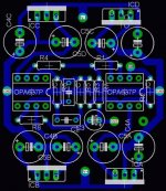
Ok, I have a few items today.
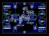
1. My "last word" on the eagle layout. See attached image, and attached files in the next post. I left enough space for larger capacitors to be substituted. Bypass capacitors are closer to the opamp power pins. The tradeoff is more signal trace length than before.
2. I had my prototype all hooked up and ready to go, but on applying power two of the LM7812's exploded. Flipping the layout once too many times I had managed to wire every regulator backwards and upside down. No really, I don't think even one pin was connected correctly. So I'll have to pull it apart and do some repairs. The layouts uploaded earlier have this error, so I'll put a corrected version here as well as on the homepage .. but do double-check all your regulators. I was so concentrated on getting all the capacitors wired properly I neglected a simple check of the Vregs...
3. On the subject of gain, cartridges, and R2, I checked out about a dozen different MC cartridges from 4-5 manufacturers. I can offer the following general guidelines:
Ok, I have a few items today.
1. My "last word" on the eagle layout. See attached image, and attached files in the next post. I left enough space for larger capacitors to be substituted. Bypass capacitors are closer to the opamp power pins. The tradeoff is more signal trace length than before.
2. I had my prototype all hooked up and ready to go, but on applying power two of the LM7812's exploded. Flipping the layout once too many times I had managed to wire every regulator backwards and upside down. No really, I don't think even one pin was connected correctly. So I'll have to pull it apart and do some repairs. The layouts uploaded earlier have this error, so I'll put a corrected version here as well as on the homepage .. but do double-check all your regulators. I was so concentrated on getting all the capacitors wired properly I neglected a simple check of the Vregs...
3. On the subject of gain, cartridges, and R2, I checked out about a dozen different MC cartridges from 4-5 manufacturers. I can offer the following general guidelines:
- Setting R2 to 1 k should give close to line-level output for the majority of MC cartridges out there.
- The Denon's an the only class exception I found. They all need larger values of R2 for line-level gain. 4.7k or 6.8k.
- Further exceptions are the Denon DL-S1 and Ortofon MC-5000. Both of these require the OP37 instead of the OP27, and R2 to be 2.2k for the Ortofon, and 15k for the Denon.
[/list=a]
I didnt run into any truly exotic sub 100uV carts on my search, if anyone could care to point one out to me ...
-r
Attachments
- Status
- This old topic is closed. If you want to reopen this topic, contact a moderator using the "Report Post" button.
- Home
- Source & Line
- Analogue Source
- Phonoclone Update