Hello all,
Very good news all around. Fran, I checked out your video. That's a handsome LT and it performs excellently. I like the straight ahead styling, it's very effective.
I'm delighted/relieved the ceramic bearings worked for everybody. I ordered four different sets from Acer Racer - clutch, brushless motor, regular, and 7x10x3, which is a bit peculiar, but interesting. So far the clutch bearing, once I got the seals off and all the grease out, seems the most promising. Acer Racer claims they are engineered differently, tighter specs, for the clutch duty. They spin very freely and seem to have just about no radial play. They also seem to run smoother and quieter than the previous bearings. Cost isn't a problem - they're about eight bucks. I'll have more to report later.
I wonder if Acer Racer is a bit puzzled by these orders. We should all e-mail them pictures of the arms.
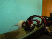
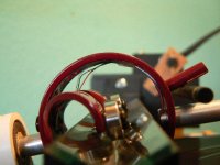
I've been playing in the shop, again. I narrowed the bearing spacing and the effective length is 4.5". It weighs 49gr. It tracks well and sounds good. It PVC-based and the sonic improvement with the paint was amazing. This arm transmits the least noise/music into the structure of any arm I've built.
I measured equal lengths of aluminum and carbon fiber tube - they weighed the same, but the carbon won the resonance drop test. The aluminum rang like a chime while the carbon just made a high pitched thunk. Maybe JRKO could tell us more about this.
I'm beginning to think this thing we've been working on - two years now for me - is just about dialed in. The basic recipe is pretty well determined. I hope that means more folks will jump in because, at this point, a working LT can be made with hand tools on an apt. kitchen table. It may not be terribly precise or beautiful, but it will work and sound good.
phivates - would you explain a bit more on your 90 degree torquing question?
Very good news all around. Fran, I checked out your video. That's a handsome LT and it performs excellently. I like the straight ahead styling, it's very effective.
I'm delighted/relieved the ceramic bearings worked for everybody. I ordered four different sets from Acer Racer - clutch, brushless motor, regular, and 7x10x3, which is a bit peculiar, but interesting. So far the clutch bearing, once I got the seals off and all the grease out, seems the most promising. Acer Racer claims they are engineered differently, tighter specs, for the clutch duty. They spin very freely and seem to have just about no radial play. They also seem to run smoother and quieter than the previous bearings. Cost isn't a problem - they're about eight bucks. I'll have more to report later.
I wonder if Acer Racer is a bit puzzled by these orders. We should all e-mail them pictures of the arms.
I've been playing in the shop, again. I narrowed the bearing spacing and the effective length is 4.5". It weighs 49gr. It tracks well and sounds good. It PVC-based and the sonic improvement with the paint was amazing. This arm transmits the least noise/music into the structure of any arm I've built.
I measured equal lengths of aluminum and carbon fiber tube - they weighed the same, but the carbon won the resonance drop test. The aluminum rang like a chime while the carbon just made a high pitched thunk. Maybe JRKO could tell us more about this.
I'm beginning to think this thing we've been working on - two years now for me - is just about dialed in. The basic recipe is pretty well determined. I hope that means more folks will jump in because, at this point, a working LT can be made with hand tools on an apt. kitchen table. It may not be terribly precise or beautiful, but it will work and sound good.
phivates - would you explain a bit more on your 90 degree torquing question?
Attachments
Hello all also:
Fran- Nice job. I think you are just about there. What did you use for the arm wand(s). I like your styling and implementation. It is going to be interesting to see what refinements are going to come about.
Doug- You have been busy. PVC wow. You say paint made a big difference. I assume you mean the red stuff on the carriage frame. I used wood, mahogany, about 1/8" thick for the vertical carriage member and wood for the bearing support rods and the arm wand. so far I've not used any damping on the wooden parts. Put some darker oil stain on the arm wand for looks only, and thin coated the frame with cyanoacrylate glue to seal it against humidity. It has turned out to be very quiet. With the amplifier off and a good loud record playing there is barely any needle talk audible. I would like to build a carriage with the double tube arms as Bo and now Fran have done. Regarding the "clutch" bearing with very small radial play. My gut feel is that taking that accommodation for small playing wows away and forcing the bearings to ride up and down the glass walls will not be as satisfactory. Otherwise I think the better bearing, less friction lower starting and running torque can only be good. Going back to Bo's insistence that getting the most signal off the record and into the amplifier was the name of the game. Introducing lossy elements into the structure, damping materials, paint, PVC, wood, imho will work against Bo's basic goals. It will help to kill resonances and feedback to the cart. So I think there may be a compromise needed. We gotta sort that out some. My wood structure definitely works better than the early one using aluminum tubing. That one needed to be wrapped with black tape and cotton thread. So I'm not convinced that using PVC is the way to go.
Fran- I was under the impression that these ceramic bearings had non-contacting shields. So I left them in place. Guess I'll remove the shields and check that out. Good Show Lads,
BillG
Hello all,
Very good news all around. Fran, I checked out your video. That's a handsome LT and it performs excellently. I like the straight ahead styling, it's very effective.
I'm delighted/relieved the ceramic bearings worked for everybody. I ordered four different sets from Acer Racer - clutch, brushless motor, regular, and 7x10x3, which is a bit peculiar, but interesting. So far the clutch bearing, once I got the seals off and all the grease out, seems the most promising. Acer Racer claims they are engineered differently, tighter specs, for the clutch duty. They spin very freely and seem to have just about no radial play. They also seem to run smoother and quieter than the previous bearings. Cost isn't a problem - they're about eight bucks. I'll have more to report later.
I wonder if Acer Racer is a bit puzzled by these orders. We should all e-mail them pictures of the arms.
I've been playing in the shop, again. I narrowed the bearing spacing and the effective length is 4.5". It weighs 49gr. It tracks well and sounds good. It PVC-based and the sonic improvement with the paint was amazing. This arm transmits the least noise/music into the structure of any arm I've built.
I measured equal lengths of aluminum and carbon fiber tube - they weighed the same, but the carbon won the resonance drop test. The aluminum rang like a chime while the carbon just made a high pitched thunk. Maybe JRKO could tell us more about this.
I'm beginning to think this thing we've been working on - two years now for me - is just about dialed in. The basic recipe is pretty well determined. I hope that means more folks will jump in because, at this point, a working LT can be made with hand tools on an apt. kitchen table. It may not be terribly precise or beautiful, but it will work and sound good.
phivates - would you explain a bit more on your 90 degree torquing question?
Bill,
I was afraid this was gonna happen - the red paint comment was just me making fun of my stylin'. The PVC just gave me nice curves to work with, it's possible damping qualities only became apparent after the arm was built. I weighed equal sized sections of ABS and PVC and was surprised that PVC is heavier even though the ABS was thicker. In other words, ABS is less dense. In the past, I've had to use heat shrink to make aluminum tube quiet, but this time it doesn't seem necessary.
We've taken this thing to the point we're discussing arcane subjects like the finer points of bearing characteristics and the resonant qualities and consequences of materials and structures.
I'll be mounting the clutch bearings some time soon and will check to see any effects in warp handling, which is where I think any lack of radial play would make itself felt. I think the ceramics seals only contact one side. I took them off just on GPs and the clutches and 4x10x4 s cleaned up much easier without them.
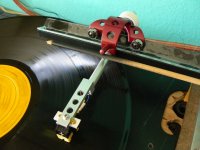
Fran - I just tried to guess Bill's angle on his first glass track. I over estimated and wound up with 120 degrees, which does get the upper edge of the glass out of the way, but I'm not sure there's any other advantage. I've been doing some thought experiments about V angles and as far as I can tell, any angle from 90 and above up to the point where torquing and skittering begins to show up will work. At this point, I think your method of mounting the sllps in 90 degree aluminum angle is the simplest, best protected, most easily attached way to go. Again, very nice work and thanks for coming to the party. Would you post some pictures here? I'd like to see some more details.
I was afraid this was gonna happen - the red paint comment was just me making fun of my stylin'. The PVC just gave me nice curves to work with, it's possible damping qualities only became apparent after the arm was built. I weighed equal sized sections of ABS and PVC and was surprised that PVC is heavier even though the ABS was thicker. In other words, ABS is less dense. In the past, I've had to use heat shrink to make aluminum tube quiet, but this time it doesn't seem necessary.
We've taken this thing to the point we're discussing arcane subjects like the finer points of bearing characteristics and the resonant qualities and consequences of materials and structures.
I'll be mounting the clutch bearings some time soon and will check to see any effects in warp handling, which is where I think any lack of radial play would make itself felt. I think the ceramics seals only contact one side. I took them off just on GPs and the clutches and 4x10x4 s cleaned up much easier without them.
Fran - I just tried to guess Bill's angle on his first glass track. I over estimated and wound up with 120 degrees, which does get the upper edge of the glass out of the way, but I'm not sure there's any other advantage. I've been doing some thought experiments about V angles and as far as I can tell, any angle from 90 and above up to the point where torquing and skittering begins to show up will work. At this point, I think your method of mounting the sllps in 90 degree aluminum angle is the simplest, best protected, most easily attached way to go. Again, very nice work and thanks for coming to the party. Would you post some pictures here? I'd like to see some more details.
Last edited:
Doug: your sense for the visual esthetic is excellent. I really think you should consider industrial design. You have an excellent balance between a look which captures the interest while at the same time follows and servers function. Do you draw any of your ideas up in sketch up that we could see. I think an assortment of different ideas would provide some real stimulus for those trying to decide how they might want their arm to look. Well done I would like to see more. Best regards Moray James.
Stylin'
Your arm is wicked awesome. As for damping or not, well I don't like the results that go with undamped systems in my carpenter world, including my truck, and I've just joined the ductseal club on my speaker tweaking. Gloss red on PVC: brilliant, literally.
My 90 degree comment is also carpenter-think; that when a force is resisted say by bearing friction there's a reaction sideways. Posts bend before they crush under load, frinstance. Popping the clutch usually results in a wavy patch on the pavement, if the torque available is sufficient. Is that "moment?"
Anyway. Great stuff. I agree with M James.
Thank you Moray and phivates for the kind words about the arm.
The Sketch Up learning curve was a bit steep for me and my working drawings are mostly crude reminders of what I've been thinking about - the one for the latest arm is literally on the back of an envelope - but I have thought about compiling the photos. I'm a sculptor, and although I haven't done much of that recently, it seems to come out sideways in my audio designs. Before I discovered Norman bel Geddes or figured out Raymond Lowey designed something other than the '53 Studebaker, my life took a couple of turns that put industrial/package design out of reach. I've always regretted that.
I think the 90 degree question deserves investigation. Ceramic bearings seem to alleviate a lot of the friction problem, but that still leaves inertial forces. I've never had much luck at trying to vector this thing out.
I don't like to hear needle talk or to hear sound from any source in the arm with a stethoscope so I've used brute force methods - neoprene, heat shrink - to tame that sometimes. I'm not sure about the consequences to the music.
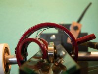
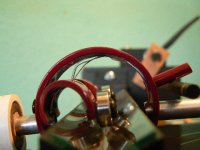
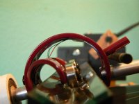
Questions from an LT skeptic friend made me take the pictures. The bearing does seem to slide rather than pivot on the back corner. In a 90 degree V, a really bad warp might make the back side of the bearing scrape a bit, but that would be extreme and momentary. A more open V keeps that from happening at all.
The Sketch Up learning curve was a bit steep for me and my working drawings are mostly crude reminders of what I've been thinking about - the one for the latest arm is literally on the back of an envelope - but I have thought about compiling the photos. I'm a sculptor, and although I haven't done much of that recently, it seems to come out sideways in my audio designs. Before I discovered Norman bel Geddes or figured out Raymond Lowey designed something other than the '53 Studebaker, my life took a couple of turns that put industrial/package design out of reach. I've always regretted that.
I think the 90 degree question deserves investigation. Ceramic bearings seem to alleviate a lot of the friction problem, but that still leaves inertial forces. I've never had much luck at trying to vector this thing out.
I don't like to hear needle talk or to hear sound from any source in the arm with a stethoscope so I've used brute force methods - neoprene, heat shrink - to tame that sometimes. I'm not sure about the consequences to the music.
Questions from an LT skeptic friend made me take the pictures. The bearing does seem to slide rather than pivot on the back corner. In a 90 degree V, a really bad warp might make the back side of the bearing scrape a bit, but that would be extreme and momentary. A more open V keeps that from happening at all.
Attachments
Vectors
Or something; my middle name is Victor, who was my dad. 50 years ago I was on the swim team in high school. We strove mightily to keep our palms moving in a pure longitudinal stroke with no, that's zero, deflection laterally. Now they say that the zig zag ours hands want to do is what works. Fish zig zag to get on their way, their way. Are they stupid?
Nature has scant use for straight lines. We REALLY want them to work. Consider the groove our stylus is asked to track. Not too linear! So when our precious gem is told to do what it has to do, a bit of wiggle room right at the beginning may be what is needed to get going.
Is this clueless? I am just guessing.
Dear clueless (phivares)...
...I don't think you can fight the Physics, however nature has a funny way of "finding" the most efficient (and thus lowest energy) solution to pretty much all physical system problems. It reminds me of engineers who engineer solution rather than look for a simpler solution.
Considering the "sliding" bearing issue as stated by dtut:If you'd like to "vector this thing out" PM or email me. I'll see what I can do (just nice simple vector diagrams in 3D). The forces acting on the stylus/cart/arm/bearings/armshaft/counterweight/tube, etc., can be diagrammed as a series of small isolated or "closed" systems. The great thing about the use of vectors is that there exists a well defined set of rules and vector mathematics that can help explain a particular system (almost) completely.
dtut: the arm you've built is pretty spectacular to look at. Kudos on the implementation.
Last edited:
My dad worked at Scripp's Institution of Oceanography in La Jolla. Scripp's, among other things, did research for the Navy, which in its effort to design faster subs, spent a lot of time looking at dolphins. There was serious Naval consternation when they found that dolphin skin ripples to accommodate micro pressures in the water, which allows them move far more efficiently than rigid structures.
Nanook, that's a very generous offer. Thank you. PM on the way.
Nanook, that's a very generous offer. Thank you. PM on the way.
Hi Doug,
Wondering what has been going on in your shop. Have you done anything with the "clutch" bearings yet? What are your results if you have used them? Things been quiet around here. Getting the cottage opened up for another season and lots of yard work. Still enjoying the LT. Did spend some time doing a much more careful setup of the entire TT and arm. No major improvements there just some better operator control with less need to be so careful using it. How about a progress report plz?
BillG
Hi Bill,
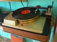
I've been hiding in my shop again. I've wanted to mount an LT on an Empire for a long time and finally got it done. Seems to work pretty well. Bass has taken on a new solidity. I just did a stethoscope check - it's silent.
The LT is running on the "clutch" bearings, now. I can't detect any difference one way or the other.
About two weeks ago, it was cold, grey, and rainy here, too cold even to work in the shop, so I got some paper and pencils to do some scaled up drawings of bearings in V troughs to see what I could find out about warp response. The back corner drops and the front corner climbs, but depending on the V angle, the drop/climb ratio can change from quite different at 90 degrees to equal at about 140 degrees. Another interesting thing is that there is a point on the bearing that remains stable, the bearing effectively rotates around it, and it rises from low in a 90 degree V to higher at more open angles. At about 140 degrees it equals the width of the bearing so with a 4x10x5 bearing, the stable point equals the axle center. Pictures would really help so I'll see if I can work something up in Paint.
Life has been scratching at the door again so I'm going to have to set the LT pursuit aside for a while. I'll still want to see what other folks have been up to.
Attachments
V troughs
Hi Doug,
Very interesting about center of rotation vs trough angle. Initially I wasn't following what was going on without pictures. Then it hit me. Pics are not necessary, a simple physical analog will do it. Using paper with 1/4" square rulings I drew track angles for 90deg and about 145deg. Then using the same rulings from the paper I drew a rectangle representing the outline of the bearing 10 units high, 4 units wide, 5 units ID. on a piece of colored card stock and cut it out with scissors. On the rolling axis I fastened a thin straight piece of card to represent the arm wand sticking out the center of the bearing. Then I placed the arm/bearing cutout into one of the V grooves previously drawn. With a push pin positioning the bearing so its contacting corners just hit the sides of the V an equal distance up from the apex of the V I then lifted the arm wand up nd down simulating a warp. It took a few tries to find the correct position for the axis of rotation. Once found mark it on the V groove. Then go on to another V groove drawing and repeat the process. It is easy to see how the point around which the bearing rotates shifts up or down as a function of V groove angle and how to select the angle to provide a track with an optimal angle for a given bearing width dimension.
The real question is what geometry will be best to use and within certain limits does it all matter. Will a shallow V allow easier or better setting of the tracking force. I would like to have a strain gauge incorporated into the arm wand or head shell so that the actual tracking force could be measured with a record being played. It may be that is the only valid way to determine tracking force.
BillG
Hi Bill,
I've been hiding in my shop again. I've wanted to mount an LT on an Empire for a long time and finally got it done. Seems to work pretty well. Bass has taken on a new solidity. I just did a stethoscope check - it's silent.
The LT is running on the "clutch" bearings, now. I can't detect any difference one way or the other.
About two weeks ago, it was cold, grey, and rainy here, too cold even to work in the shop, so I got some paper and pencils to do some scaled up drawings of bearings in V troughs to see what I could find out about warp response. The back corner drops and the front corner climbs, but depending on the V angle, the drop/climb ratio can change from quite different at 90 degrees to equal at about 140 degrees. Another interesting thing is that there is a point on the bearing that remains stable, the bearing effectively rotates around it, and it rises from low in a 90 degree V to higher at more open angles. At about 140 degrees it equals the width of the bearing so with a 4x10x5 bearing, the stable point equals the axle center. Pictures would really help so I'll see if I can work something up in Paint.
Life has been scratching at the door again so I'm going to have to set the LT pursuit aside for a while. I'll still want to see what other folks have been up to.
Hi Doug,
Very interesting about center of rotation vs trough angle. Initially I wasn't following what was going on without pictures. Then it hit me. Pics are not necessary, a simple physical analog will do it. Using paper with 1/4" square rulings I drew track angles for 90deg and about 145deg. Then using the same rulings from the paper I drew a rectangle representing the outline of the bearing 10 units high, 4 units wide, 5 units ID. on a piece of colored card stock and cut it out with scissors. On the rolling axis I fastened a thin straight piece of card to represent the arm wand sticking out the center of the bearing. Then I placed the arm/bearing cutout into one of the V grooves previously drawn. With a push pin positioning the bearing so its contacting corners just hit the sides of the V an equal distance up from the apex of the V I then lifted the arm wand up nd down simulating a warp. It took a few tries to find the correct position for the axis of rotation. Once found mark it on the V groove. Then go on to another V groove drawing and repeat the process. It is easy to see how the point around which the bearing rotates shifts up or down as a function of V groove angle and how to select the angle to provide a track with an optimal angle for a given bearing width dimension.
The real question is what geometry will be best to use and within certain limits does it all matter. Will a shallow V allow easier or better setting of the tracking force. I would like to have a strain gauge incorporated into the arm wand or head shell so that the actual tracking force could be measured with a record being played. It may be that is the only valid way to determine tracking force.
BillG
BillG,
That was ingenious and I'm glad you confirmed what I thought I'd found. I'm pretty much convinced that the trough angle probably isn't significant and the variable pivot point is mostly an interesting artifact. Glass slips in a 90 degree aluminum angle is an easy path and should work just fine. Maybe Fran has more to report although I think he's been enjoying his Schroeder arm recently. I hope you're able to do the strain gauge investigation.
Would you be willing to write up a glass cutting primer for our purposes here? I don't seem to have the knack and I want to check out a 90 degree trough.
BillG,
That was ingenious and I'm glad you confirmed what I thought I'd found. I'm pretty much convinced that the trough angle probably isn't significant and the variable pivot point is mostly an interesting artifact. Glass slips in a 90 degree aluminum angle is an easy path and should work just fine. Maybe Fran has more to report although I think he's been enjoying his Schroeder arm recently. I hope you're able to do the strain gauge investigation.
Would you be willing to write up a glass cutting primer for our purposes here? I don't seem to have the knack and I want to check out a 90 degree trough.
Hi Doug,
Here is a note on cutting glass. The web is full of tutorials and other directions for how to cut glass. I've been reviewing some of them and find they are better than anything I could come up with. My have included a list of URL`s that will cover the subject rather well. I also include a few tips I find helpful.
There is one video which discuses scoring and the importance of clean glass with no dust or foreign particles which could interupt the score. It also has audio emphasizing the sound of the cutting of the score line. Hearing that sound for comparison to the sound you are getting from your cutter is a big help. The score line must run uninturupted from start to finish. You can start the score a tad in from the edge (1/16") in from the edge but run off the glass at the end of the score.That runoff is where to start breaking the glass off. The score does not need to be deep.
The next point is PRACTICE. you need to get the feel for scoring and breaking the glass. Get a stack of broken stuff from your local glass merchant or hardware store to practice on. Key to scoring a good line is how you hold the cutter (a nice new one, but they last a good long time). The wheel should be parallel to the direction of cut and perpendicular to the glass surface. The wheel and glass surface should be lubricated with oil, kerosene in the States, parafin in Dublin. The lubricated wheel gives a much cleaner score line with fewer and smaller chips along the score line. I have found that one doesn't get as audible an indication of the scoring action with lubrication as doing it dry and it is more difficult to snap the glass off at the line. This problem could well be the result of faulty technique on my part than anything else. If you now know how to produce a good score line I guess we can move on to snapping off the "slip" of glass you want.
More years ago than I care to enumerate I learned or imagined this but have been unable to coroborate it in the here and now of the internet. When you score the glass you set up a fracture plane (or something to that effect) on which your glass breaks off. Right after you do the scoring this fracture plane is "hot" in the sense of ready to be broken. Wait a short while and it cools off. As I understand it the cut is self healing and the molecular bonds are re-established. So for the best cut snap off your sample within the next few minutes before it cools off. On one web site I did see reference to the cool off. There was no other reference to this phenomenon. I assume the author was aware of it. I did find one reference to the self healing and it emphasizes the cut starts to heal quickly.
Now on to snapping off at the line. For lots of hints and techniques see the websites dealing with the topic. Read a bunch of them there is much of interest and practicle knowledge there. Basicaly there are just a couple ways I have found work for the narrow 1/4" wide slipe I have used. I loose as many as I win so I'm still gaining skills. For the narrow slips I use two pair of old side cutting pliers, box joint not slip joint. Mine are more or less smooth jawed, a bit of cross hatch for gripping but no sharp teeth and no uneven surfaces to press into the glass. Then I pad the jaws with 3 or 4 layers of masking tape. Grab the piece to be broken with the pliers at the end where the cutter wheel ran off the glass one pair just to the left of the score and one pair to the right of the score. Hold the pliers in front of you, score side of glass facing you and apply firm pressure rotating your right hand clockwise and your left hand anticlockwise. The web will detail 6 other ways of snapping off the glass including just grabbing it with your fingers and rotating as just described and placing something round like a nail or a drill bit immediately under the score line at the score end and pressing down on the glass at the edges of the finished piece. I've used hardeware store glass cutters successfuly, but they tend to wear out quickly. Better ones are available on line. My present cutter has a diamond embeded in a metal pen style holder that has been in my tool box for years but only recently have I really learned to use it. Good luck with your venture. Cutting glass is a skill worth having.
Running the Score on glass is easy by following these instructions
GLASS CUTTING TIPS
How To Cut Glass - YouTube
The secret (a good one)
Rgds to all,
BillG


Bill,
Thanks for the links and your own information. I'll take your advice about just getting some scrap and making little ones out of big ones until some of the little ones have straight edges.
Hi,dtut
you can cut the glass tube with bellow tool and water,it's so easy!

here is my achievement

Eaglebear,
Thanks for posting the photos of your glass cutting technique. That's very nice work and will be helpful to builders who want to clone the original Cantus more closely with a tube instead of, for instance, a trough.
What kind of glass tube did you use and where did you source it? And would you go into more detail about the tool you used? I'm not familiar with a "bellow tool." Are those diamond cutting wheels?
Please post more about your project as you go along.
Eaglebear,
Thanks for posting the photos of your glass cutting technique. That's very nice work and will be helpful to builders who want to clone the original Cantus more closely with a tube instead of, for instance, a trough.
What kind of glass tube did you use and where did you source it? And would you go into more detail about the tool you used? I'm not familiar with a "bellow tool." Are those diamond cutting wheels?
Please post more about your project as you go along.
hi,dtut
The tube is a piece of glass tube for liquidometer,I got it from Chemical instrument store.Here are some pics for detail process
1\marking the cutting line by marker pen

2\The cutting tool(electric hand-held grinder & diamond cutting piece )


3\I cut the tube in bathroom,hanging-up the grinder and cutting under the tap


- Status
- This old topic is closed. If you want to reopen this topic, contact a moderator using the "Report Post" button.
- Home
- Source & Line
- Analogue Source
- Opus 3 Cantus parallel tracking arm