perhaps something like this, except with a solid "tube"
Going external,it would be easier with a calibrated s/s rod,which is perfectly dimensioned,externally,and bearings made of industrial plastics, eg Ertalon.
B.L.
.
If the rollers are riding on the outside of the tube, then why not just use TWO U-groove bearings riding on a rod? It's certainly cheaper and simpler that way.
.
.
If the rollers are riding on the outside of the tube, then why not just use TWO U-groove bearings riding on a rod? It's certainly cheaper and simpler that way.
.
An externally hosted image should be here but it was not working when we last tested it.
.
Hi all,
Been following this with interest.
I have sketched out some ideas (good old pencil on the back of an envelope).
Using 3 bearings on an inverted channel, 2 on the front face wide spaced, 1 on the back face central, with separate knife edge/single points for the up/down.
Inspiration is the Trans-Fi Audio - Terminator Tonearm
John.
.
If the rollers are riding on the outside of the tube, then why not just use TWO U-groove bearings riding on a rod? It's certainly cheaper and simpler that way.
.
An externally hosted image should be here but it was not working when we last tested it.
.
And use a Teflon rod ,with all the benefits.Excellent idea.Less glitzy,than the glass tube,perhaps,but more easy,for DIY.
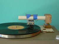
This Opus clone was cobbled together as a proof of concept project and this is its Initial Public Exposure. Obviously, without PVC and blue masking tape, I'd never be able to build anything so, again, what EC8010 called "rustic."
The bearings are $5/pair remote control model car parts. I removed the seals and lubricant so they roll more freely. The PVC interior is highly polished. Horizontal movement (rolling bearings) is quite good - no hitches or stuttering as long as the record is clean. This arm does not like dirty records. Vertical movement (sliding bearings) of the arm is stiff. Setting the VTF is difficult and, although the arm does follow warps, the stylus winds up doing a lot of the work. The polished glass tube and carefully chosen bearings would help. Figuring out the arm mass and relative weights of head shell and counter balance was trial and error. I probably didn't get optimal results.
Regardless, it works and it's definitely DIY possible.
The sound has a remarkable presence and is very enjoyable with a deep 3D stage and the best bass - detailed and musical - I've ever heard from my system. The sound is transparent so voices and instruments are clearly delineated.
After seeing the Opus pictures, I just couldn't help myself. It's encouraging to have obsessions turn out well.
Attachments
Doug: nice knock up. I do like the spirit level nice touch. Clear Audio make the "STATEMENT" yours might be what you can afford to build after the divorce so perhaps we should call it the "SETTLEMENT".
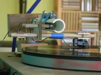
Try giving the trolley assembly a degree or two of downward tilt to provide a little help to make things roll along easily. Great to hear that it works and sounds so good.
Is it good enough to temp you to give up on the thread suspension arm that you have been working on? I can't quite make out from the picture but one of those tip mounted record brushed might provide a tad extra trolley drive and also provide some relief for the cantilever and its suspension. Nice job Doug I am sure that this will inspire some other folks to try some ideas out. Do you think you might be talked int trying out a metal tube for comparison? Thank you for posting your pictures. Best regards Moray James.
Doug I just had a simpler idea to check out friction of the PVC tube. Make a little dam at the end of the tube with putty or the like and with an eye dropper insert just enough alcohol to wet the bottom of the tube. Single Malt Whiskey works best for me but that seems such a waste. Running wet should reduce overall friction quite a bit and you can see if there is any significant improvement. Faster and easier than building a metal tube. Regards Moray James.
Moray,
She got the Hi Fi, I got the tube - something like that?
Thanks. I hope others will take a shot at an Opus clone, but I also hope that some of the other ingenious ideas and approaches from this thread will become working models - like BillG's glass-lined V trough. Part of doing my half-assed builds is to show it doesn't take an engineering degree and fully-staffed machine shop to produce something workable and rewarding. Funky materials and a home shop are just fine for a first approximation. Big bucks and obsessive precision can come later, if they're justified.
I noticed, looking down the tube, that a bit of trolley angle - either for or aft - might help, but I haven't quite figured it out yet. The cartridge is a Shure w/dust brush. I thought it might help with lateral movement, but I've tried the arm with the brush up and down and didn't notice any difference.
I'm still working on the string arm - that's my baby and it still has some growing up to do yet.
I've got copper tubing that's the right diameter, but that's for another day. In the meantime, I'll try the alcohol idea and report back. If I ever make a Schroeder quality version of this thing maybe I'll consider putting single malt in it, but not 'til then.
.
If the rollers are riding on the outside of the tube, then why not just use TWO U-groove bearings riding on a rod?
Well, um, yes. Hehe, of course!
 I did think of that and completely forgot about it. Silly, really, as I had to do something similar for a big sliding repo camera rig. 2 rails instead of 1.
I like Doug's effort a lot. But I was thinking about the bearings on the top of the rod (v-bearings, of course) and just a normal pivot for vertical. Don't know if it would be any better, but it might.
Some fun thinking going on here, and some nice building, too.
When I discussed the normal vertical pivot idea with Bo he was adamant that that was one of the things which Lou Souther had done and that the arm worked better without the free swing pivot because it would resonate and also because it was not as rigid in other words there was too much loss of energy with a free swing vertical pivot. The free pivot will work well it's just that the more rigid version works better. You can see which version Clear Audio chose for their top of the line arm just as Bo did for the same reasons. Too bad CA did not come up with an original idea but at least they chose the better working one. I think that pretty much tells the story.
With respect to inside Vs outside for bearing position well it is the same deal outside you are trying to keep the arm balanced with gravity looking to pull it off balance. Inside of the tube the trolley can ride up the wall (to permit the cartridge to ride a warp) but gravity pulls it back down to centre position for you. Its not a free lunch but it's as close to one as you are ever going to get. The more you look at it Cantus is a very clever design. Regards Moray James.
With respect to inside Vs outside for bearing position well it is the same deal outside you are trying to keep the arm balanced with gravity looking to pull it off balance. Inside of the tube the trolley can ride up the wall (to permit the cartridge to ride a warp) but gravity pulls it back down to centre position for you. Its not a free lunch but it's as close to one as you are ever going to get. The more you look at it Cantus is a very clever design. Regards Moray James.
Last edited:
Its not a free lunch but it's as close to one as you are ever going to get. The more you look at it Cantus is a very clever design.
No free lunch but trying different things offer free play. I agree that the Cantus is a very clever design and I understand the theory behind it but not many people have tried or even designed a mechanical linear tonearm like that before so people are just itching to try all the variations. The Cantus has already been designed so the fun for me is to find an alternative that can work just as well with even less hassle and that's where the fun is at. For me, it's an intellectual exercise and for others it's a mean to get a quality tonearm at an affordable price. Thanks for providing the design details though.
.
Yeah, thanks Moray for the great info. Good to know what others found in their quests.
I am surprised that the vertical pivot caused trouble. Sometimes you never know until you try!
Of course the idea of the bearings on top of the tube is not to do it better, but make it easier for DIY. It's certainly going to be a bit "tipsy".
I am surprised that the vertical pivot caused trouble. Sometimes you never know until you try!
Of course the idea of the bearings on top of the tube is not to do it better, but make it easier for DIY. It's certainly going to be a bit "tipsy".
thanks Moray...
UR my hero
Make no mistake, creativity has its own rewards. The Cantus should be respected for what it is (and for having longevity in the marketplace), a very clever idea implemented as simply as possible. I am pretty shocked that it (and the Continuo) hasn't received more attention in the audio press. As it is Rauna's design, perhaps it has never received a lot of reviews, so as to keep sales "enough" without creating a huge demand.
Things that I have always respected in all designs are simplicity, longevity and good design to begin with. The turntable itself is unique in this way, how many upgrades has Linn had over the first 25 years of the LP12? And as far as I know the tonearm has been on the market as long...
Hi,
Not all of which actually upgraded the sound of the deck but that's another story.
Should there be any of you actually using a Nottingham Analogue Paragon arm, I'd be interested to learn how Tom Fletcher (the man behind the company) tackled the basic problems.
A PM would be welcome, I don't want to spoil this great thread.
Ciao,
how many upgrades has Linn had over the first 25 years of the LP12?
Not all of which actually upgraded the sound of the deck but that's another story.
Should there be any of you actually using a Nottingham Analogue Paragon arm, I'd be interested to learn how Tom Fletcher (the man behind the company) tackled the basic problems.
A PM would be welcome, I don't want to spoil this great thread.
Ciao,
Should there be any of you actually using a Nottingham Analogue Paragon arm, I'd be interested to learn how Tom Fletcher tackled the basic problems.
Various versions of the Paragon. Judging by the last two pictures, I think it uses V-groove bearings.
An externally hosted image should be here but it was not working when we last tested it.
An externally hosted image should be here but it was not working when we last tested it.
An externally hosted image should be here but it was not working when we last tested it.
.
Hi,
Thank you for the pics.
One of the reasons I asked, besides having tons of admiration for what Tom Fletcher achieved, is that he was convinced that a tonearm, be that a tangential one or a radial tracking one, should have at least one physical contact with it's base in order to evacuate unwanted vibrations.
I am convinced he's right as other than going for a very high pressure airborne tonearm cartridge induced vibrationswill tend to travel back and forth.
This is something we learned while developing the Goldmund parallel tracking arms and also saw confirmed in Tom's brilliant radial tracking uni-pivot arms.
Anyway, back to topic...
TA,
I think that Mr. Fletcher did a fine job of the visual esthete's of the Paragon arm being very clean and understated very business like. I think that with air or magnetic arms or tables for that matter you have an unfortunate disconnect and compliance issues which are easily dealt with in a mechanical design but not so otherwise.
Bo's premise is to keep things as rigid as possible so that the motion of the tip translates into the maximum amount of electrical energy.
I wonder are there any mechanical engineers here who might offer some suggestions as to calculating the approximate COG of the arm then possible configurations could be considered to lower the assembly as close to the record surface as possible and maintain stability. The COG should be just below the pivot point.
While I play with ideas I have decided to get a Cantus and Continuo then if I decide to experiment I will have the real thing to compare to. Is there anyone here who is also interested? If so you can PM me for a discussion. Best regards.
ANOTHER IDEA
Here's another thought in my head. If I use two round rods in parallel on the horizontal plane, I can use two U-groove bearings gliding laterally without any vertical movement. And then I can place a dual-pivot housing with two spikes and an armwand on top for vertical bearing. This way I can have more control or damping on the vertical plane such as using fluid or even magnet to stabilize the bearings to lessen the rocking. The two spikes can be blunted or use two small ball bearings or flatter surface to reduce vertical movement. And the two U-groove bearings need not to be linked together physically, which can reduce over all mass. Of course, you can always add a linkage between the two bearings. And the bearing wells can be filled with viscous fluid for damping vertical movement.
I hope the crude pictures gets the point across.
Ugroove bearing on horizontal plane.
.
Here's another thought in my head. If I use two round rods in parallel on the horizontal plane, I can use two U-groove bearings gliding laterally without any vertical movement. And then I can place a dual-pivot housing with two spikes and an armwand on top for vertical bearing. This way I can have more control or damping on the vertical plane such as using fluid or even magnet to stabilize the bearings to lessen the rocking. The two spikes can be blunted or use two small ball bearings or flatter surface to reduce vertical movement. And the two U-groove bearings need not to be linked together physically, which can reduce over all mass. Of course, you can always add a linkage between the two bearings. And the bearing wells can be filled with viscous fluid for damping vertical movement.
I hope the crude pictures gets the point across.
An externally hosted image should be here but it was not working when we last tested it.
Ugroove bearing on horizontal plane.
An externally hosted image should be here but it was not working when we last tested it.
.
Last edited:
- Status
- This old topic is closed. If you want to reopen this topic, contact a moderator using the "Report Post" button.
- Home
- Source & Line
- Analogue Source
- Opus 3 Cantus parallel tracking arm