Thanks for your comments...
if the arm has only two balls in the trolley assembly and works this well you have your proof and i would not argue that it works very well. From the first photo I saw I was thinking about the Souther arm and another design which is very similar but which uses a captive air bearing that was patented in the early 60's I think. In my mind I cannot help but think that a three point contact trolley would have a stability advantage as well as a possible structural advantage thought it will add mor to the moving mass. The inside sheltered position of the trolley is a clever idea as even normal amounts of house dust will catch up to you. You need a clean machine.
I thought about the comment on the ars range of motion and why that was special, the arm does not move up and down it only moves forwards and backwards and horizontaly. I tried to recall listening to Lou discribe how his arm worked and his answers to my non understanding questions. I think I have ben able to answer one of my own questions. A longer arm geometry would not be good as it would move towards the cartridge moving up and down and you want ti to move forward and backwards so it can track the surface if the record in a parallel manner.
If I am getting a better understanding of this arm please feel free to further enlighten me and if i am off bass please correct me. If you have some clear photos or drawings of the trolley I would very much like to see them so I can get a better understanding of this arm. Lastly I seem to recall Lou Souther telling me that a very short arm was necessary and desireable, the cantus is longe than Lous arm could you comment on that? Thank you and a special thanks to Peter at Pentacone for his help in discribing the arm and for telling me about the slot at the back. I was starting to feel like the mind freak was making this thing work.
Anders Reply
Hello Anders,
I tried to tell Opus3 about you....and he said "Anders" is my Very Good Friend from "long Time"
I wish he could speak proper english like wht I do...!
LuvP.
PS. Thanks for teaching the "Trying" Afficionado's, a little further on their paths. It might only take the thirty three years that I have been Trying to understand!!!
P.
OK, I give in Moray!!
Are you going to tell everybody...like I told you privately....Or am I???
Do not forget, at this stage, that our 12 Hour conversation was Private!!!
Who has told them about the secret slot....did you have permission to let them know....IDIOT??
And don't , for G*d's Sake let them in on the Dust!!!
Now look, just between me and you...Forwards and Backwards is from the Back of the Turntable Chassis towards the Front...NOT across the Platter to the Spindle!! I hope I've made myself CLEAR NOW!!
And Opus3 will NEVER allow you to see a Diagram...no matter how nicely you BEG!!
Now, just so you realise that I am spending a Fortune attempting to help you create your own Arm...The trolley is so stable, it does not Move at all!!!
Anders, Can you explain this any clearer? I seem to be having a bit of trouble!!
By the way, the Glass Tubes swings around quite easily, thus making it MUCH better than the Pathetic Souther!!!
Poor Lou, if only he listened to Mr OPUS.
T.T.F.N.
P.

sorry folks, haven't watched this for a while...
Moray,
the Cantus looks interesting. I can pretty well backwards engineer it if you like. ...but----three bearings can create a "wobbly leg" effect. If running on a plane (flat surface) then yes 3 is better than 2, but in the tube... I think 2 are better than 3.
stew
Moray,
the Cantus looks interesting. I can pretty well backwards engineer it if you like. ...but----three bearings can create a "wobbly leg" effect. If running on a plane (flat surface) then yes 3 is better than 2, but in the tube... I think 2 are better than 3.
stew
Hey Stew...
so the assembly you are suggesting would consist of two ball in cup bearings which are mounted to either end of a rectangular plate, one bearing turned up at one end and the other bearing turned down at the opposite end. And if I follow Andres the bearings would be offset from the centre line of the rectangular plate so one bearing tip on one side of the plate and the other bearing tip on the opposite side of the plate. Two holes in the plate to mount the rods that insert into the tube via the slot.
I suppose you could also mount the bearings in the exact centre of the plate with one bearing on the front side of the plate pointing up and the other bearing on the other side of the plate facing down. But this orientation depends upon perfect balance of weight on the two rods. If you place the bearings at the ends of the plate it ought to be more stable.
Am I making sense? Is this what you had intended? Have got to learn to use sketchup so I can draw what I am thinking.
perhaps Anders would comment?
I figure that this arm has been in production (and so in the public domain) for what must be twenty years? DIY eats very little if any of a manufactures sales. I am considering ideas for a similar arm not a copy. That said knowing how the Cantus is designed would be very educational. The likelyhood of my ever building one of these is VERY little as I need a new project like I need a hole in my head. Personally I would be more inclined to purchase a prebuilt unit but the design concepts fascinate me. On the other hand crude tinkering to prove concepts could be entertaining. A good example is the Ikea arm design. To take such a project to the point of being the equal of a production unit is a huge task and one I would prefer to leave to the manufacturer.
Thanks Nanook I look forward to your sketch. Regards.
I apologize if I am being redundant but I want to point out again the reason Souther/Clearaudio tonearm resting on three rollers , which make a plane, is to lock in for horizontal movement only to ride on the two quartz rails and vertical movement is taken care of at the gimbal bearings below at the hanging mechanism. If one is to use two rollers, it would create a rocking front to back motion, thus the vertical arm movement. My concern with the Cantus arm is that the two rollers are cylindrical and seating on a glass tube would create too much contact points, at least four. Wouldn't it be better to have V-grooved rollers riding on a blade, therefore less contact, less friction and more precise vertical pivot? Just a thought.
I do like the simplicity of the Cantus design - anything that does not require an air pump is thumbs up in my book. I wish we can explore more options in the pursuit of tangential tracking without resorting to air-bearing ad nauseam. It's more fun and inventive to come up with non-air-bearing designs, such as rails, rollers, magnets, multiple pivoting (Thales tonearm), hinges, etc, etc...
Here's fellow in Japan uses linear motion ball bearing bushings to make a linear tracker.
Directdriver: it is my understanding from those who I have spoken with who have hands on experience with Cantus that the roller bearing assembly has superb contact with the surface of the glass track and the bearings are considered to be rigid except for their horizontal rolling motion. The bearing race assemblies in the roller bearings have been designed to have a small amount of slack (self damped by lubricant and sealed) which permits the arm enough motion to track record warps. It is this rigidity which accounts for the arms tremendous control and dynamics. The intent is to transfer as much energy from the cartridge (tip motion in the record groove) into electrical energy as is possible. This is achieved by reducing physical motion in the arm to a minimum.
I had though along similar lines to your possible suggestion of the roller on a knife edge. I had envisioned two captive single ball in cup bearings one at either end of a sled assembly that holds the arm. These would be very small and provide both horizontal motion as well as a pivotal axis point for arm motion, a rolling knife edge bearing if you like.
I discussed this with Bo himself and found his comments to be very interesting. Bo told me that as soon as the arm was allowed to freely pivot to provide forward and backward motion to track warps you have also allowed it to resonate at some frequency. You are then loosing energy and adding distortion through that motion. The purpose designed slack which permits the race assembly to move as a whole so the arm can navigate small record warps and which is damped is all that is required to play through a warp while maintaining the concept of keeping the assembly as rigid as possible. Tremendous bass control and dynamics are two of the primary characteristic qualities that owners of the Cantus repeatedly comment on regarding its performance.
......My concern with the Cantus arm is that the two rollers are cylindrical and seating on a glass tube would create too much contact points, at least four......
Just want to point out that there is an edge on the bearings so there are only two contact points.
BR,
Anders
Cantus arm
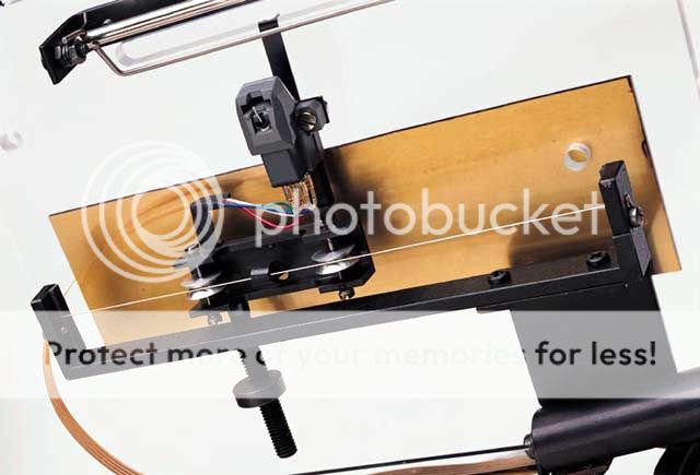
As far as I know early versions did have a ridge on the side edge of the roller bearings upon which the arm could pivot but this is not any longer part of the design on current Cantus arms as the rocking action was not considered desirable. The new version is said to be more stable and perform better as a result. The attached drawing shows the old style bearing assembly. Regards.
As far as I know early versions did have a ridge on the side edge of the roller bearings upon which the arm could pivot but this is not any longer part of the design on current Cantus arms as the rocking action was not considered desirable. The new version is said to be more stable and perform better as a result. The attached drawing shows the old style bearing assembly. Regards.
Attachments

.
Thanks to Moray and Bappe for clarifying things and providing more design details. Now that I saw the drawing, it makes sense to have a flange bearing using the ridge as a rolling knife edge to reduce contact area. Judging from previous pictures I was confuse about that and thought the two ball bearings were flat circumference cylindrical shape that would create too much contact area and, hence, friction. This early version is really not much different conceptually from a V-groove bearing riding on a blade or the reverse, a rolling blade riding on a v-groove track. I am curious about the current version if, as you said, it eliminates the ridge and how it behaves vertically. If having more contact area is a good thing then a U-groove bearing riding on a round shaft would help stability, right? This is a fascinating design and its simplicity makes it very DIY-able for this community. Thanks again for the drawing.
By the way, the tonearm on the obscenely expensive Clearaudio Statement turntable uses, I believe, similar concept. Except the armwand is above the bearings whereas the Cantus is below the bearings. Check pictures and websites.
.

.

.
Thanks to Moray and Bappe for clarifying things and providing more design details. Now that I saw the drawing, it makes sense to have a flange bearing using the ridge as a rolling knife edge to reduce contact area. Judging from previous pictures I was confuse about that and thought the two ball bearings were flat circumference cylindrical shape that would create too much contact area and, hence, friction. This early version is really not much different conceptually from a V-groove bearing riding on a blade or the reverse, a rolling blade riding on a v-groove track. I am curious about the current version if, as you said, it eliminates the ridge and how it behaves vertically. If having more contact area is a good thing then a U-groove bearing riding on a round shaft would help stability, right? This is a fascinating design and its simplicity makes it very DIY-able for this community. Thanks again for the drawing.
By the way, the tonearm on the obscenely expensive Clearaudio Statement turntable uses, I believe, similar concept. Except the armwand is above the bearings whereas the Cantus is below the bearings. Check pictures and websites.
.
.
.
Directdriver: perhaps you can re read post # 31. The roller bearings in the current version of the Cantus are designs to permit the internal bearing race a small amount of controlled motion. The bearing race can move within the roller assembly without disturbing the horizontal motion of the sled or carriage.
Here is a Quote from Bo Hansson outlining the design goals of the Cantus
"There are of course a lot of different ways to make a tonearm. My goal for Cantus is in short:
The cartridge tip shall read the information in the track, on the same spot as it was cut, This is not possible with a pivoted tonearm.
The cartridge shall have a stable reference and not be able to "swing" i.e. there shall not be a fundamental resonance in the system. This is not possible with a pivoted arm. To solve this there are two contact points, which make the carriage hold the cartridge so it can move side ways but not get into resonance.
There shall not be resonators coupled to the cartridge, such as the "organ-pipe" resonance that is common with most existing tonearms. I mean that when you have a tube almost one foot long coupled to the cartridge, the tube itself resonates on two foot and four foot tones approximately 300Hz and 600 Hz and overtones of this. By making the tonearm tubes very short, the resonance is forced up to higher frequencies, and by using a very small diameter for the tubes the resonance is further reduced significantly. You can easily hear a tonearm resonance when you put down the cartridge in a quite track on the record. When you compare the sound from Cantus with most of other tonearms you will find Cantus playing the empty track, much quieter than other arms.
There shall not be any kind of energy storage in the system (flexible materials). All mechanical energy shall be converted to electric output from the cartridge.
The vertical movement of the arm riding the record, shall be damped. In Cantus damping is provided by using ball bearings with a little side ways play. This means the contact point in the bearing is changed when the tonearm moves up and down. As the contact point is changed there is automatically a damping, because it's not a resonant point. This is perhaps difficult to understand, so please give it some time and thought." End Quote.
I hope this helps to make it clearer how the arm works.
Please note that I was in error about the bearing assemblies in this arm. I had been under the mistaken impression the bearings were lubricated with a light grease this is NOT the case, the Bearings are clean with no lubricant and are sealed. I apologize for this error and thank my dear friend Peter at Pentacone for correcting me
Here's one that uses V-groove bearing riding on a string, much like the Clearaudio Tangent.
.
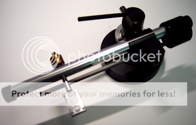
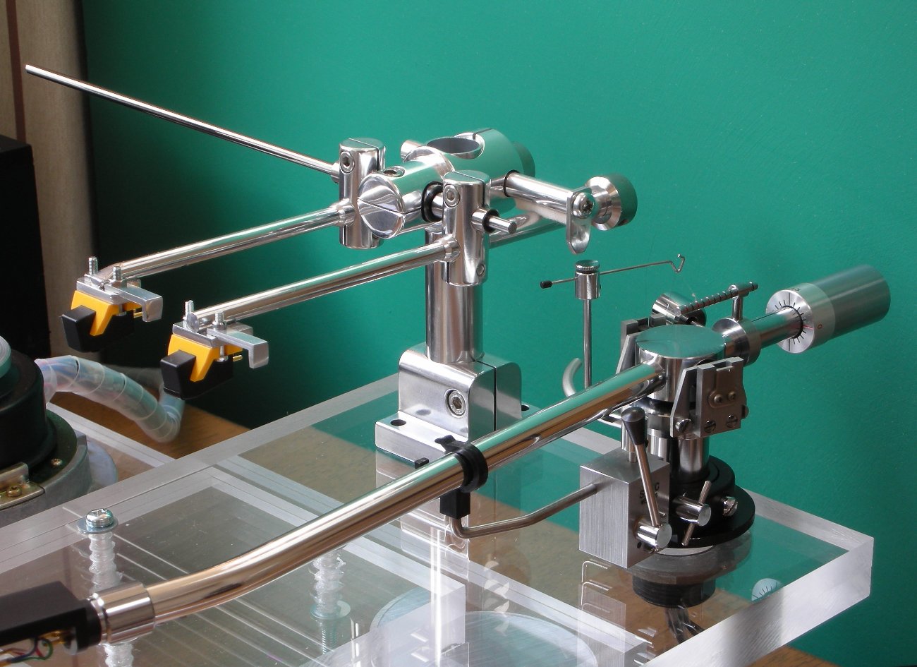
Here's a rather rare one, Nottingham Paragon linear tracker. Rather elegant looking.
.
.
Here's a rather rare one, Nottingham Paragon linear tracker. Rather elegant looking.
.
The Nottingham Paragon looks very nice but the picture does not show much of the mechanical detail did you find any other pictures of it? The first arm shows that even one tensioned thread can support a linear arm. This arm will have a resonance as it allows the arm to freely swing up and down on the V-groove rollers which is something the Cantus eliminates. Thanks for posting these interesting pictures.
Here are few more images on the Paragon tonearm. It's really rare. Judging by the look of it, it's essentially two V-groove bearings moving laterally with a short armwand.
.
.
___________________________________
Here's one using linear motion bushing made by THK for horizontal movement. More pictures in the website and I believe the DIYer can reduce the mass even further if he simply glue the armwand directly below the bushing without using a coupler.

.
.
An externally hosted image should be here but it was not working when we last tested it.
.
An externally hosted image should be here but it was not working when we last tested it.
.
___________________________________
Here's one using linear motion bushing made by THK for horizontal movement. More pictures in the website and I believe the DIYer can reduce the mass even further if he simply glue the armwand directly below the bushing without using a coupler.
.
.
- Status
- This old topic is closed. If you want to reopen this topic, contact a moderator using the "Report Post" button.
- Home
- Source & Line
- Analogue Source
- Opus 3 Cantus parallel tracking arm