Re. 'cascoding', if I send you the circuit diagram, can you tell me how to introduce a cascode ... so as to remove the '133' divisor?
Regards,
Andy
Why don't you just post it?
If your RIAA values are sufficiently high that the JFET input impedance is a significant factor then you are likely to have problems with thermal noise.
Not sure I follow you, DF96?
I use a 511K Gate-to-ground shunt res before the 2nd gain stage. I use this value to provide a nice high Zin for the 1st gain stage (plus passive RIAA network) to drive.
The phono stage is the quietest I have ever heard.
Andy
Why don't you just post it?
Here it is (a pdf) - hopefully this works.
")
Andy
Attachments
R13 is much too high.
Thanks for your input, JG. I understand that R13 - and R22 - are, being in series, noise-inducing resistors but I was under the impression that 100 ohms was needed as a 'Gate stopper' on a JFET gain stage to prevent oscillation?
What value do you recommend?
I use Vishay reses here - which I was told were low noise?
Andy
I use Vishay reses here - which I was told were low noise?
Any resistor produces thermal noise, also known as Johnson noise. The thermal noise only depends on the temperature, bandwidth and resistance, not on the type or brand of the resistor.
On top of that, the resistance of a resistor has random variations that can cause extra noise when there is current flowing through it. This is known as excess noise or 1/f noise. It varies a lot depending on the construction of the resistor. For example, wirewound resistors have very little 1/f noise and carbon composite resistors have quite a lot of it.
As there is almost no current flowing through a gate stopper resistor, excess noise is not a concern for gate stoppers, but thermal noise can be a problem, and it is independent of the type and brand of resistor.
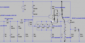
This is a version with an NPN cascode. The four extra diodes are supposed to be red LEDs. The 12 V is now distributed more or less equally between the NPN and the JFETs, so the circuit can't handle large signals as well as it used to.
Attachments
Last edited:
How ever good this 100 Ohm resistor is, it‘s thermal noise alone totally destroys your efford to parallel Fet´t to get lower voltage noise. You could wind a coil over it though. Then the stopper action is only at rather high frequencies.
That is a great idea, Joachim. As I understand it, the Grid stopper res is there to prevent HF oscillation ... so if the res/coil combination only works at HFs, we still get oscillation prevention but don't have the noise penalty at audio frequencies (as the signal goes through the coil wire, not the res).
Can you suggest how many coils of wire I should make up? The ID of the coils needs to be, say, 6mm - to clear the resistor.
Andy
Last edited:
I do that with tube phono stages and it works great. i would try 6 to 8 windings.
i usually fix the coil with some nail lacquer or similar.
Thanks, Joachim,
I will use 7 coils in my next build.
Andy
OK, now I can see the circuit; this makes discussing it much easier!andyr said:Not sure I follow you, DF96?
I use a 511K Gate-to-ground shunt res before the 2nd gain stage. I use this value to provide a nice high Zin for the 1st gain stage (plus passive RIAA network) to drive.
The 511k and 0.1uF cap form a low pass filter at about 3Hz. This means that provided the 511k resistor plus whatever is in parallel with it does not vary by more than about 10-20% you are fine. So you want the JFET input to be greater than 5M, which I think you will achieve. My comments about thermal noise were on the assumption that you have a highish impedance RIAA network with the 511k forming a significant termination. In your case this is not true, so thermal noise will be dominated by the 47k at the input to the network.
OK, now I can see the circuit; this makes discussing it much easier!
The 511k and 0.1uF cap form a low pass filter at about 3Hz. This means that provided the 511k resistor plus whatever is in parallel with it does not vary by more than about 10-20% you are fine. So you want the JFET input to be greater than 5M, which I think you will achieve. My comments about thermal noise were on the assumption that you have a highish impedance RIAA network with the 511k forming a significant termination. In your case this is not true, so thermal noise will be dominated by the 47k at the input to the network.
Thank you, DF96.
Yes, it would seem that even with the 2nd gain stage being a matched quad of JFETs, the JFET Zin wil be much > than 5meg.
I have been told that 47K at the input to the network is unnecessary - so I will be reducing this to 33K for the next build. Lowering this resistor should reduce thermal noise, right?
Andy
The 47k is absolutely necessary. Together with C2 it sets the LF frequency where the RIAA response starts. If you change its value you need to recalculate the entire network.
Sure, DF96 - I know that. But I have the equations which calculate all the RIAA network values - so I can easily redo them with a 33K series lead-in res.
My only concern is ... what is the uppermost value I can use for the Zout of the 1st gain stage (ie. the shunt gain res) in order to drive 33K well:
* 1K2?
* 1K54?
* 2K?
Andy
Perhaps I misunderstood you; I thought you were saying that the resistor is unnecessary, when perhaps you were saying that it doesn't have to be 47k.
Whatever value you choose for R1 (and every other resistor) has knock-on effects elsewhere so up to you to recalculate. You have the equations; if they are correct then you can redesign the circuit. However, you may need to be aware of any simplifying assumptions in the equations: for example, do they assume that the RIAA network is fed from a voltage source? Where does the network actually start?
The circuit you showed us feeds the RIAA network with 47k in series with (2k in parallel with the first stage output impedance).
However, you may need to be aware of any simplifying assumptions in the equations: for example, do they assume that the RIAA network is fed from a voltage source? Where does the network actually start?
Referring back to the diagram I attached earlier, the RIAA network starts with R1 and R47 and ends with [R16 in parallel with the Zin of the 2nd JFET stage].
These resistors set the values for the actual RIAA components - R2 & R3 and C1 & C2.
The circuit you showed us feeds the RIAA network with 47k in series with (2k in parallel with the first stage output impedance).
R1 defines the Zout of the 1st gain stage.
Andy
R1 defines the Zout of the 1st gain stage.
Andy
That's an example of a simplifying assumption, because the first-stage FETs as well as the current source have a finite output impedance of themselves.
That's an example of a simplifying assumption, because the first-stage FETs as well as the current source have a finite output impedance of themselves.
Aah, OK - thanks, Marcel.
My electronics knowledge is rudimentary ... I was relying on what a friend (who designs amps for a living) told me.
Andy
- Status
- This old topic is closed. If you want to reopen this topic, contact a moderator using the "Report Post" button.
- Home
- Source & Line
- Analogue Source
- Zin of the 2nd stage of a JFET-based phono stage when a pair of JFETs is used?