I've studied this circuit rather extensively, both with simulations and directly with transfer functions, and I don't see how it can work as described. It comes reasonably close, within < 3dB, and in some cases extremely close, but I've found some assumptions and calculations that don't seem to be valid.
1. Using a single-pole formula that delivers attenuation at 10Khz ref 1Hz is not correct for a filter with two poles and a zero. For example, the formula delivers not -13.73dB but -13.65dB for the RIAA case. However the RIAA transfer function does deliver -13.73dB at 10KHz ref 1KHz. And if you feed -13.73dB into the 1-pole formula you get not RIAA's 2122Hz but 2103Hz. So in the RIAA case the calculations have been ignored and the already-known values have been used in the preamp instead. This calls into question all the other cases where the calculations were used.
Notes:
1. The 1-pole formula on p80, with the huge square root, can be expressed rather more simply as 10000/sqrt(10^(-dB/10)-1), (dB <= 0, which is what you actually have).
2. This is derived by solving dB = 20*log10|1+wj/wc| for the cutoff frequency wc, where dB is known (and negative) and w=10000. There are some 2PI's missing, but they cancel out (or can be ignored as mere frequency-scaling), giving the result in Hz.
3. If you change the numerator from 10,000 to X you then have a solution for the turnover frequency given the attenuation at X Hz instead of 10KHz.
2. I can't make sense of the formula for R5. I don't know why it uses the 'base frequency' instead of the actual F3, and I certainly don't know why you would add 1Hz to it. I also find in both simulation and transfer-function calculation that this formula's results for R5 lead to several extra dB (about 4 in the RIAA case) in the bass, and that using F3 instead of (FBase+1) yields a much more correct solution.
In any case this (F4) piece of the design seems over-optimistic. The formula for R5 is designed to adjust the gain such that the gain at F4 is F3/F4 the gain at F3, in the hope that this will yield 0dB at 1KHz to make (1) above work. In practice it doesn't actually do this, and it can't. Consider F4=1KHz, which is an included case in the design: it can't deliver both a +3dB turnover at F4 and 0dB at 1Khz. It does work overall for RIAA, I suspect because of the coincidence that 1KHz is very nearly the geometric mean of 500.5 and 2122, but it fails in most other cases, and the higher the value of F4 the worse the error. And the formula seems to assume that the gains at F3 and F4 are linearly related, which is only true if you use the real (variable) F3, not the 'base frequency'.
It's notable that the only cases where simulation graphs are provided are the cases where either:
(a) the bass or the treble setting is 'flat' (bass='flat' is a valid case for using the 1-pole formula, and treble='flat' doesn't over-exercise the F4 problem above), or
(b) RIAA, where the results of the 1-pole formula were not used, as the required values are already well-known in advance.
It's notable that the F5 values given for various well-known curves in the table are rather different from those given by other sources such Audacity, PSpatial Audio, MidiMagic, Russell Fisher, Peter Copeland, etc. (not that these are universally in mutual agreement of course).
To be certain I'm not just committing some trivial error somewhere, I've calculated all this several different ways, with both my own software and Excel, and simulated it in two different implementations of Spice.
I hope to be corrected about all this if I'm wrong anywhere.
EJP
I built it, but instead of an array of mechanical switches, I used Analog Devices switches and an Arduino micro-controller. It's a bit of a kludge on a PCB as I have two tubes of LM4562 DIP left over!
The results are on my other computer which I won't have access to for 3 weeks, but will report back.
The results are on my other computer which I won't have access to for 3 weeks, but will report back.
Thanks, looking forward to it.
I'm working on the formula for R5. I have an analytic basis for it that makes sense to me in terms of the transfer function, but I keep finding things I've missed ;-) I have my errors down to < 1dB when calculated my way, and I've also eliminated most of the ~4dB error mentioned above when calculated the published way. So we are converging on a solution ;-).
I also have a formula for calculating T5 given T3, T4, and the dB attenuation at 10KHz ref. 1Khz, but it needs tidying up before I can publish it. It's rather long :-|
1. Using a single-pole formula that delivers attenuation at 10Khz ref 1Hz is not correct for a filter with two poles and a zero.
It's referred to the low-frequency asymptote, or equivalently to 0 Hz, otherwise I agree completely. At best it's a coarse approximation when you compare the response at 10 kHz to the sort of flat part between F4 and F5.
2. I can't make sense of the formula for R5. I don't know why it uses the 'base frequency' instead of the actual F3, and I certainly don't know why you would add 1Hz to it. I also find in both simulation and transfer-function calculation that this formula's results for R5 lead to several extra dB (about 4 in the RIAA case) in the bass, and that using F3 instead of (FBase+1) yields a much more correct solution.
Indeed, the dimensions don't even make sense - adding a dimensionless constant to a frequency?
I checked if there are any corrections on the Linear Audio website, but didn't find any for this article (no letters to the Editor either).
Last edited:
My proposed formula for R5:
R5 = (R4(R3+R4)(1+R1/R2)R6/(|1+F4j/F3|)
where
R4/(R3+R4) is the attenuation at the voltage divider R3/R4
(1+R1/R2) is the gain through IC1
R6 is explained below
|1+F4j/F3| = sqrt(1+(F4/F3)^2) is the gain of the transfer function for T3 at F4. The 'missing' factors of 2PI cancel out.
This is algebraically derived by equating the two transfer functions through IC2 at F4:
Z7/R6 = Z7(R4(R3+R4)(1+R1/R2)R6/|1+F4j/F3|/R5
and multiplying by R5R6/Z7, where Z7 = Z(R7||C2) = |R7/(1+R7C2wj)| is the impedance of the feedback network around IC2, but as it cancels out it is unnecessary to even write it out fully, let alone calculate it for any given frequency w.
This result now needs to be multiplied by a small constant near 1.1, to provide some desired non-unity ratio between the gains of the unfiltered and filtered paths. In the case of RIAA the factor is 1.11655, but I don't imagine it is the same for all combinations of T3 and T4. I am still working on what this number actually means. I imagine it has something to do with the ratios between T3, T4, and T5. In a way I would have expected it to be much smaller, say < 0.414, to cause the total gain at F4 to be under 1.414 or slightly < +3dB, but it doesn't seem to want to work that way.
For RIAA this yields R5=6.7267K; the published calculation yields 6.663K; the actual recommended value in the published preamp is 6.735K. The discrepancy between the last two values is noted in the article but not really explained, or rather explained away with some hand-waving about component tolerances.
In transfer-function calculations, R5=6.7267K gives RIAA accuracy of +/-0.0004dB. R5=6.663K via the published formula yields +/-0.0337dB. The actual value of 6.735K used in the article does better at +/-0.0083dB.
Note that the bass end of this circuit can never be 100% accurate. The performance is flattered considerably by relating the maximum error to the average error so as to give a +/- error. In reality there are only positive errors at the bass end and zeros at the treble end. The T5 part of the circuit is 100% accurate, but the bass end can never be accurate as it is summing a circuit obeying T3 with another that isn't.
This formula yields values for R5 given F3 and F4 as follows (all corrected by the factor of 1.11655 which remains a work-in-progress):
| F3 | F4 | R5 |
|---|---|---|
30 | 150 | 2.2118E+04 |
30 | 200 | 1.6730E+04 |
30 | 250 | 1.3437E+04 |
30 | 300 | 1.1222E+04 |
40 | 400 | 8.4165E+03 |
45 | 450 | 7.4813E+03 |
50.04872 | 500.4872 | 6.7267E+03 |
100 | 500.05 | 6.6347E+03 |
63 | 625 | 5.3861E+03 |
80 | 800 | 4.2083E+03 |
100 | 1000 | 3.3666E+03 |
Last edited by a moderator:
The attachment is as far as I got. I haven't checked if it is equivalent to your calculation. I included the schematic of the part that we discuss, redrawn to prevent copyright issues.
@jan.didden ejp found several errors in a Linear Audio article from 2013. Do you still put corrections/letters to the retired Editor on your website?
@jan.didden ejp found several errors in a Linear Audio article from 2013. Do you still put corrections/letters to the retired Editor on your website?
Attachments
Marcel
Have you run the numbers on this formula? It yields R5=6.7273K and a maximum RIAA error in transfer-function calculations of 0.0000000000000817dB. Spectacularly correct, my congratulations. It's not equivalent to my calculation, as I was aiming for equal gains where you were aiming straight at T4. But I'm encouraged to see that we both have the same view of the transfer functions, and there are of course many similarities, in some cases after substitutions, for example R4/(R3+R4) = 1/(R3/R4+1).
Note that I calculated with your formula using the actual R and C values, not the ideal F3/F4 values, and this is important in a practical circuit so as to avoid propagating component-selection imprecision. F3min for example is not 30Hz with the published component values but 30.0292345hz.
I have further observations on T5 but I'll leave those for another day.
I had already contacted Jan about this. He is prepared to put in a belated letter to the editor. I've already tried to contact Gary Galo but no luck so far.
For the record, Marcel's formula is as follows:
where w4 = 2piF4. The formula is given here in the form most suitable for actual component calculation, i.e. using the actual values of previously chosen components, so as not to propagate component-selection inaccuracies. It can be expressed in a perhaps more intelligible form using time constants or frequencies instead, and in this form it is easy to see where the errors in the published formula came from. My thanks again to Marcel for this.
It is also possible to verify from this form, or indeed from the transfer function itself, that the circuit does indeed provide a disc-replay transfer function, with two poles and one zero, contrary to my assertion above.
The R5 values calculated by Marcel's method are as follows:
R5 = R6*(1+R1/R2)*R4/(w4*R3*R4*R1-R3-R4)
where w4 = 2piF4. The formula is given here in the form most suitable for actual component calculation, i.e. using the actual values of previously chosen components, so as not to propagate component-selection inaccuracies. It can be expressed in a perhaps more intelligible form using time constants or frequencies instead, and in this form it is easy to see where the errors in the published formula came from. My thanks again to Marcel for this.
It is also possible to verify from this form, or indeed from the transfer function itself, that the circuit does indeed provide a disc-replay transfer function, with two poles and one zero, contrary to my assertion above.
The R5 values calculated by Marcel's method are as follows:
F3 | F4 | VDG R5 |
30 | 150 | 2.5252E+04 |
30 | 200 | 1.7825E+04 |
30 | 250 | 1.3774E+04 |
30 | 300 | 1.1223E+04 |
40 | 400 | 8.4173E+03 |
45 | 450 | 7.4820E+03 |
50.04872 | 500.4872 | 6.7273E+03 |
100 | 500.5 | 7.5661E+03 |
63 | 625 | 5.3919E+03 |
80 | 800 | 4.2086E+03 |
100 | 1000 | 3.3669E+03 |
Today is another dayI have further observations on T5 but I'll leave those for another day.
")
I took the old values from the Linear Audio article, and EJP's new T5 values and simulated (Multisim). Then compared with the calculated values for T3, T4 and T5 using Laplace for the RIAA, Columbia, 100/1k and 40/400 (AES):
Attachments
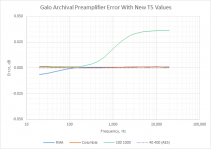
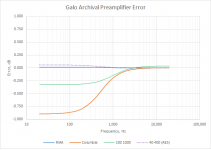
The graphs represent the difference between the theoretical gain, and the simulated gain with the values Galo used, and those calculated by Marcel.I haven't given any values for T5. Only for R5, and they are Marcel's, not mine, or at least they are results of his formula.
What do the graphs mean?
Interesting, Galo has an article in the current issue (October 2022) of AudioXpress on the Sumiko 78 RPM cartridge.
OK well to comment, the only one that's correct in the second graph is RIAA, and that's the only one for which the calculated value for R5 wasn't used. A tweaked value was used, closer to the value given by Marcel's formula.
Viewers should note that the scaling in the Y axis differs by a factor of 20 between the two graphs.
It would be interesting to know exactly what is meant by 'using Laplace'.
Viewers should note that the scaling in the Y axis differs by a factor of 20 between the two graphs.
It would be interesting to know exactly what is meant by 'using Laplace'.
Create a voltage component in SPICE which uses the Laplace transform, n'est ce pas? Easy enough in LTSpice or Multisim.It would be interesting to know exactly what is meant by 'using Laplace'.
Another observation: look at the article's Figure 12 showing simulated response curves for the bass EQ settings. You can see that the dB values at each curve's T4 point are not consistent. Calculated dB values at the T4 points using Marcel's R5 in each case show standard deviation of 0.03 dB. In other words all 12 are within 0.1 dB of correct.
In this context: most SPICE packages have a function block which takes equation parameters and models the frequency response of that equation. The RIAA curve can be shown roughly by RCA's bad drawing of "New Orthophonic" or exactly by specifying poles/zeros. The SPICE function is often called Laplace after some old guy.It would be interesting to know exactly what is meant by 'using Laplace'.
https://www.analog.com/en/technical...pplying-the-laplace-transform-in-ltspice.html
Property Symbol(s) PSpice Library Description Required Default Units
NUM LAPLACE ABM Numerator of Laplace transform Yes 1 none
DENOM LAPLACE ABM Denominator of Laplace transform Yes 1 + s none
"In mathematics, the Laplace transform....is an integral transform that converts a function of a real variable (usually, in the time domain) to a function of a complex variable (in the complex frequency domain, also known as s-domain, or s-plane)."
- Home
- Source & Line
- Analogue Source
- Archival Phono Preamp by Gary Galo