I have on old turn table which uses this AC 24V motor. The control board is shot so I'm looking for the cheapest DYI way I restore 33.3 and 45 speeds to this motor. My knowledge is all DC so I'm a bit out of my depth. I was able to breadboard the motor with from the spec doc to verify it's fine. The old board uses a bunch of obsolete chips so repairing it is not an option. I'm really looking for a pretty turn-key solution but I'm willing to put it together myself. The motor is/was smooth so I really want to build around it.
I did read up on the SG4 in this forum and while very cool it's a bit complicated for what I need after adding an amp etc.
Here is the spec doc and the exact motor I have. Any suggestions or help would be appreciated. The existing power supply is 24V AC but I'm open to changing it if I can keep the cost down.
https://docs-emea.rs-online.com/webdocs/0250/0900766b80250dc4.pdf
The old board uses a bunch of obsolete chips so repairing it is not an option.
Repairing the old board is probably your easiest option. Does it use a sinewave chip like an 8038 or does it generate a square wave that gets molded into a sine?
Either way, the output amp and the ps are already in place. Troubleshooting it would really be worthwhile, as the chances are good something simple needs replacement.
It is another matter if you are dead set to not repair it

It is using an ICL8038, even the knock off NTE864 isn't made anymore. It's also using PA60 opamp which I think is likely the problem. It doesn't look to me like anyone makes a pin compatible drop-in for both of these. I'm not dead set on replacing the control board but I'm well enough into troubleshooting it I'm close to dead set.
Interesting that a dual opamp is used. Is the phase splitting done in front of the amp?
It would be easy to verify the opamp is faulty with a scope. Or even with a soundcard. A replacement daughter-board with a chip amp would be an easy fix. There is nothing special about the PA60 other than perhaps the formfactor. There may just not be sufficient room for add-on boards.
Building the entire lot from scratch is certainly more involved. You basically have a choice between a digitally synthesised sine or an analogue oscillator. Once frequency switching is involved the analogue solution starts looking complicated. The digital oscillator may be as sophisticated as the SG4 or as simple as a bare Arduino board. A reasonably powerful chip amp is still essential. Being deeply prejudiced towards class D noise generators for me that means some kind of class AB chip amp. Add a power supply and it becomes a fully blown project.
Again AC is not my wheelhouse, but looking at the traces it looks like each internal amp is driving half of the motor phase. I wonder if I could replace the amp/driver side with something like this DRV10974 3-Phase Sensorless Motor Driver - TI | Mouser
Or maybe I can split out into two different amps. Using a multimeter to diagnose this seems like a dead end. I'll have to borrow a scope to get further. I'm inclined to punt and build something digital and just interface to the AC motor but I think that will get expensive quick.
Or maybe I can split out into two different amps. Using a multimeter to diagnose this seems like a dead end. I'll have to borrow a scope to get further. I'm inclined to punt and build something digital and just interface to the AC motor but I think that will get expensive quick.
I wonder if I could replace the amp/driver side with something like this DRV10974 3-Phase Sensorless Motor Driver - TI | Mouser
No, you cannot. Any dual channel chip amp will do the job just fine. 2 x LM3886 is probably an overkill, but will work fine. What is the supply voltage?
this AC 24V motor....
I think it is a 12V motor. And that the datasheet you link is for similar motors but NOT this one. Please compare the model number carefully digit by digit.
My reading is that this is a 12V motor. (The capacitor is rated 2X the supply, this is the "24V" on the top line.)
If so, then a simple 12VAC filament transformer should spin it up to 600RPM. And probably be approximately the right speed for one of your two choices.
The '8038 may be out of production but you can find them in kits from Vellemann or CanaKits, or take pot-luck on eBay. Also look in Futurlec. However, unless someone has been poking around in there, IMHO it is very unlikely to have gone bad.
It would be REAL good to have an oscilloscope to know if you have signal and how big.
The PA60 "opamp" is NOT an ordinary 19 cent opamp but a many-Watt Power chip. It is also a very odd choice; Apex never sold cheap. As it is capable of far more power than the motor should want, death seems unlikely unless the heatsinking was none.
A 12VAC load at 4 Watts is 36 Ohms. 12VAC in a straight amplifier demands a 34VDC power supply. This and the dual nature implies the PA60 was working "bridge", needing >17V supply, with 24VDC a reasonable pick. You can replace the PA60 with two power chips which will stand 24VDC and make 2 Watts in 18 Ohms. Look for >5 Watts in 8 Ohms, two of these (or a dual) will do the 4 Watt 36 Ohm load easily.
I am out of touch with current small audio power amp chips. (The one I am thinking of went EoL about 20 years ago!) The Chip Amp section folks know what's hip today.
(BTW: a 20 Watt 8r audio amp will work. Got an old half-dead Sansui stereo and space for it to sit?)
With a dual amp the "phase split" can easily be done by cross-coupling the two amplifiers. Some care is needed if the amps are not unity-gain stable.
Last edited:
Well I have some results. The power supply is putting out 120Hz oddly at 20V AC. The next two screen shots show the output of the timing chip before the PA60DX in 33 and 45 mode. The power switch does nothing on the board but activate the PA60 and at the moment it doesn't even do that. All of these traces are with the power switch off, but I tested with it on and they were the same.
I checked all the basics. Switches switch, resistors resist and caps are not shorted. I'm starting to suspect the PA60 is to blame, nothing on the scope except on the input pins with the sine wave in the photos.


I checked all the basics. Switches switch, resistors resist and caps are not shorted. I'm starting to suspect the PA60 is to blame, nothing on the scope except on the input pins with the sine wave in the photos.
I did a bit more troubleshooting today and I see that half the phase is being amplified and the other is not (motor is not spinning I can feel it is getting power spasms). I've pulled the PA60 and on the breadboard with DC it seems to be working on both sides so I'm a bit stumped. Of course my test circuit is a very basic non-inverting op-amp, and the board for the controller is a bit beyond my skills to reverse engineer. I'll post some photos of the board if that helps.
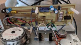
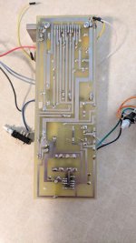
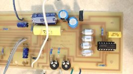
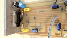
Here are some photos of the board. Ignore the black spot by the PA60DX, I replaced that and didn't clean up the board.
The board is still not working Timing works, the pots adjust the signal going into the PA60 and the motor jiggles but does not spin when you hit the power.
The board is still not working
Timing works, the pots adjust the signal going into the PA60 and the motor jiggles but does not spin when you hit the power.Attachments
This is all a bit confusing. Could you recap?
1. Is the dc power supply ok? Forget the scope. What reading do you get from a voltmeter set to DC and AC ranges at the rails?
2. Are both phases present at the inputs of the power amp? At what voltage? An AC voltmeter reading will suffice.
3. What do you get at the power amp outputs?
1. Is the dc power supply ok? Forget the scope. What reading do you get from a voltmeter set to DC and AC ranges at the rails?
2. Are both phases present at the inputs of the power amp? At what voltage? An AC voltmeter reading will suffice.
3. What do you get at the power amp outputs?
AC I'm getting 40V peak to peak, 20V RMS. DC reads zero since it's an AC power supply.
Both phases are going into the power amp at 1.3V On the output side I'm only getting one phase and the voltage is jumping around, the other side is not showing any voltage. I've replaced the power amp so it has to be something else.
Both phases are going into the power amp at 1.3V On the output side I'm only getting one phase and the voltage is jumping around, the other side is not showing any voltage. I've replaced the power amp so it has to be something else.
AC I'm getting 40V peak to peak, 20V RMS. DC reads zero since it's an AC power supply.
Both phases are going into the power amp at 1.3V On the output side I'm only getting one phase and the voltage is jumping around, the other side is not showing any voltage. I've replaced the power amp so it has to be something else.
OK. Clear now. My question about the DC supply clearly referred to the dc supply of the PA60DX. Have you measured it?
Your oscillograms, assuming they can be trusted, show a very reasonable frequency entering the PA60DX and an entirely unreasonable 120Hz exiting. This can be either a bad measurement, or blown/died out caps of the dc supply. Before going any further i suggest you make sure the dc supply rails actually carry +/-20v or thereabouts.
For a low voltage 2 phase AC motor an Arduino controlling a STMicro's L6470 (a.k.a "dSPIN") 3A, 8-45V bipolar stepper motor driver should work.
Arduino Nano ~ £1 & L6470 ~£8 on Ebay.
It's intended as a micro-stepping driver for stepper motors.
However, good luck with the repair.
Arduino Nano ~ £1 & L6470 ~£8 on Ebay.
It's intended as a micro-stepping driver for stepper motors.
However, good luck with the repair.
For a low voltage 2 phase AC motor an Arduino controlling a STMicro's L6470 (a.k.a "dSPIN") 3A, 8-45V bipolar stepper motor driver should work.
What is the advantage of using the L6470 vs Arduino pwm outputs alone? Just the integrated drivers, or is there more? Thanks.
- Status
- This old topic is closed. If you want to reopen this topic, contact a moderator using the "Report Post" button.
- Home
- Source & Line
- Analogue Source
- DYI motor controller help for Saia UFR1 AC motor