Dear all
I am currently building a phono stage and need a circuit to replace the usual 10x SUT so I can feed the rig with a MC cartridge.
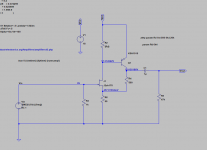
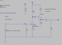
After lots of reading I found the Sziklai pair (JFET + BJT) that can do the job.
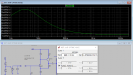
My simulations show outstanding results as far as THD goes but I am wondering why the best results are obtained only if using minimal current throu the jfet.
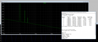
R2 sets the current on the jfet so if I use R2 = 500 I have 1.3mA Ids but THD is 0.047%
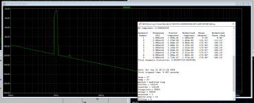
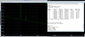
When using R2 = 6400 I only have 0.147mA Ids but THD goes down to a minimum of 0.002%
I know that for best results I should run the jfet near it's Idss (8mA) but in this case the simulation seems to indicate quite a different result.
Now the question is: How low can I run Ids in the input jfet ?
Looking forward for your input
Best
Ricardo
I am currently building a phono stage and need a circuit to replace the usual 10x SUT so I can feed the rig with a MC cartridge.
After lots of reading I found the Sziklai pair (JFET + BJT) that can do the job.
My simulations show outstanding results as far as THD goes but I am wondering why the best results are obtained only if using minimal current throu the jfet.
R2 sets the current on the jfet so if I use R2 = 500 I have 1.3mA Ids but THD is 0.047%
When using R2 = 6400 I only have 0.147mA Ids but THD goes down to a minimum of 0.002%
I know that for best results I should run the jfet near it's Idss (8mA) but in this case the simulation seems to indicate quite a different result.
Now the question is: How low can I run Ids in the input jfet ?
Looking forward for your input
Best
Ricardo
Attachments
Member
Joined 2009
Paid Member
Be careful with Sziklai. I've simulated it a lot over the years and mostly it looks great. I've built it into various stages of amplifiers and have found that it does not always sound good. In fact half the time I have ripped it back out, the other half of the time it sounded great. I conclude that you must prototype it, build it, try it out - don't waste so much time going in circles trying it on paper, use the simulator to get parts into the right operating range / resistor values - then just get some parts and build it. You will learn 10 times as much.
...I know that for best results I should run the jfet near it's Idss (8mA) but in this case the simulation seems to ...
Why?
This is a feedback amp. Higher internal gain will lead to lower simulated distortion. Gain will peak around the point that JFET current is slightly higher than PNP's Base current. Which is near what you report.
Why worry about distortion? The MOST you could ask out of it is like 100mV; anything more will clip your MM-input phono stage. So 10mV input at-most. THD is likely to be below point-oh for almost any working condition.
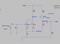
*HISS* may be lower at high JFET current. However as drawn the hiss level is the 50 Ohm resistor, not the unavoidable ~~10 Ohms of the MC cartridge, so not "optimum hiss".
You "could" reduce R4 R6 to 100r and 10r, get the hiss down. To take full advantage you want to run the JFET a lot warmer than 0.15mA, near 1mA. However the higher current seems excessive. But actually the operating point is NOT well-defined, being the Vgs of the JFET at some small current.
I am uncomfortable (and unsure) about 16V across the JFET. Gate leakage (hiss) increases. Since the gate circuit is super low impedance this may not matter. However I think the thing could eat 5V not 18V.

- Status
- This old topic is closed. If you want to reopen this topic, contact a moderator using the "Report Post" button.
- Home
- Source & Line
- Analogue Source
- Sziklai jfet input MC pre pre