Hi,
I came across this schematic from a multi piezo guitar preamp. The question isn't instrument related, but more about interfacing input, that's why i decided to post here.
The stage that interest me is so the input from piezos summed at C22 cap (ingnoring individual outputs stages driven byQ1-Q6).
Can you explain me the purpose of not decoupling piezo sensor with a cap, and using what seem to me beeing a servo (IC1B => +U) ? So what is the input impedance ? Is it a way to make impedance seen by Q7-Q12 really high at low frequencies ?
That is the only schematic i found using this kind of topology with piezo.
Thanks,
Damien
Attachments
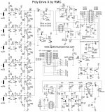
The Piezo elements have infinite impedance (resistance) at DC and so need no coupling cap.
IC1b is configured as an integrator/servo. R51 and C15 mean that no audio is present at the opamp output (the cap effectively 'shorts all AC'). The high value of R51 mean that the integrator works down to very low frequencies.
That average DC voltage output from the opamp is referenced to ground (the non inverting input). So this voltage is used to bias all the preamp stages...
What happens now is that all the stages will be a little different in DC characteristics but the summed point of all the outputs (R40/51 junction) is maintained at zero volts by the servo action.
So the DC conditions on each preamp stage will be a little different to each other, while the final output is held at zero volts.
The input impedance is mainly determined by the 1.5 meg resistor on each input, at least at DC. At AC you have the shunting effect of the small caps to take into account.
Thanks ! It's really clear. Do you have any clue on why it is done this way against a simple resistor to ground on each input ?
If i try suppose something... maybe doing this way, high input resistor to +U only add noise at near DC frequencies ? Can it be something like it ?
If i try suppose something... maybe doing this way, high input resistor to +U only add noise at near DC frequencies ? Can it be something like it ?
Its just a design choice really. Doing it this way absolutely determines the DC conditions as applied to IC1a as all the FET outputs are summed to zero volts.
If you used a resistor for bias with no servo, then the voltage at the summing point would drift about a lot due to thermal drift in the FET's. So doing it this way precisely defines the operating point.
If you used a resistor for bias with no servo, then the voltage at the summing point would drift about a lot due to thermal drift in the FET's. So doing it this way precisely defines the operating point.
Another possible reason is that it defines the gain more accurately. With the servo, each FET works into a predetermined load (fixed at one end to zero volt).
Without the servo you could have one FET at say +2 volts output and another at -1.5 and so on. That would mean each FET stage sees what amounts to a different load... and a load that changes with drift. The summing point voltage would be an undefined value that wandered about.
Without the servo you could have one FET at say +2 volts output and another at -1.5 and so on. That would mean each FET stage sees what amounts to a different load... and a load that changes with drift. The summing point voltage would be an undefined value that wandered about.
- Status
- This old topic is closed. If you want to reopen this topic, contact a moderator using the "Report Post" button.