Hi everyboady,
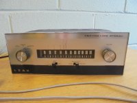
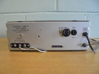
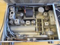
I have just boght a Leak Throughline 3 Stereo in pristine condition. I think I was fortunate, this is like a sleaping beauty. Outside as well as inside, no trace of human action, rust or dust. No component was replaced and valves are the original ones. My intention is restauration/refurbishing as much as can be.
So, for the beginning I had revival the PSU with low voltage as 110 volt getting 230 volt after some hours. I checked the multy section el-cap an was OK also checked some voltage poins and seamed OK also.
After providing a decent aerial and conection with my sistem (Nagra PLL preamp and DIY OTL Tim Mellow power amp) I stared listening.
The audition was much under my expectations. The sound was dull and absent of dinamic even on mono as stereo I was allready not expecting too much from the modest inside decoder.
That's why I am asking some hepl, where to start and what to do next.
By the way I own allready a nice valve decoder from Fischer, the MPX-100 which I intend to refurbish too and cope with the Leak tuner.
Thanks in advance.
Victor
Attachments

Last edited:
You should find this article interesting.
— LEAK Troughline Repair and Tuning—
— LEAK Troughline Repair and Tuning—
High value resistors tend to drift more than lower value; over 500k. Smoothing capacitor may need attention as will the decoupling and coupling capacitors. Whatever you do, DO NOT touch the tuning or tank capacitors, (across the tuning coils). It will never be as it should afterwards!
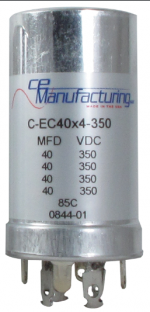
The PSU capacitor already changed with a new multisection F&T 4x50uF/500V I wonder if cathode bypass caps has to be changed as they are almost ceramic As I intend to get rid of the modest decoder, I don't see any other coupling caps. I shall go strait from the multiplex out to my Fisher MPX-100. What do you think about?
Last edited by a moderator:
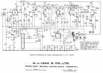
You are right in case I'll take mpx from the cathode follower but... I think previeus LEAK 3 was better taking the mpx before C51 (attached the diagram) an leave the follower for mono opperation if needed.Only the electrolytics suffer. If voltages read OK then probably OK to go straight to an FM decoder.
Check C53.
Attachments
Now I stared up with my restoration.
First stepp was measuring resistors (all of them) Pulling out the tubes I asume i can check all of them without unsoldering. The result was not verry promising as many of them were out of 10% tolerance.
The worst were:
R2=166k(220k)
R3=115k(100k)
R5=30,7(33)
R7=380k(680k)
R8=378k(680k)
R9=14k(68k) can be a mesuring fault, I have to unslder
R10=41k(33k)
R11=18k(47k) can be a mesuring fault, I have to unslder
R15=123k(100k)
R19=206k(470k)
R25=452k(470k)
R25=121k(100k)
R27=52k(47k)
R30=815k(680k)
R36=56k(47k)
R38=12k(10k)
All cheramic capacitors I asume are all right
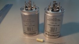
The electrolotics I have allready changed all with modern one as well as the C47 and C53 with MKp.
As I intend to use an external MPX decoder from Fisher(MPX 100) I did not care about the internal decoder compoments.
Your opinion shall be usefull to me. Shall I change all resistors or else?
First stepp was measuring resistors (all of them) Pulling out the tubes I asume i can check all of them without unsoldering. The result was not verry promising as many of them were out of 10% tolerance.
The worst were:
R2=166k(220k)
R3=115k(100k)
R5=30,7(33)
R7=380k(680k)
R8=378k(680k)
R9=14k(68k) can be a mesuring fault, I have to unslder
R10=41k(33k)
R11=18k(47k) can be a mesuring fault, I have to unslder
R15=123k(100k)
R19=206k(470k)
R25=452k(470k)
R25=121k(100k)
R27=52k(47k)
R30=815k(680k)
R36=56k(47k)
R38=12k(10k)
All cheramic capacitors I asume are all right
The electrolotics I have allready changed all with modern one as well as the C47 and C53 with MKp.
As I intend to use an external MPX decoder from Fisher(MPX 100) I did not care about the internal decoder compoments.
Your opinion shall be usefull to me. Shall I change all resistors or else?
I had remake the calculations, Lawrence was right, large part of resistors revial better tolerances than 10%. Nevertheless R9 was too low and athers where too high especialy R3, R10, R26, R27, R30, R36 R38, Which I suppose are out of range. I shal start slowly, slowly to unsolder and change them with Kiwame as they are carbon type and claim to be noninductive. I can use also AB as I have a lott but I am afraid not to be so stabile.
Before you start removing parts and upgrading them to supposed better ones, do you have an FM stereo generator that you can use to align this tuner?
Some of the parts of this tuner have been selected for specific characteristic not just the capacitors. Replacing them with a part that has a different temperature coefficient for example will result in undesirable drift, etc.
Some of the parts of this tuner have been selected for specific characteristic not just the capacitors. Replacing them with a part that has a different temperature coefficient for example will result in undesirable drift, etc.
Unfortunately I don't have the gear to realign. But some resistors values are far out of the specs. Nevertheless, the tuner works but I am especting much better sound as I have heard one sonding excelent. This one sonds dull, lack of dinamics and space.Before you start removing parts and upgrading them to supposed better ones, do you have an FM stereo generator that you can use to align this tuner?
Some of the parts of this tuner have been selected for specific characteristic not just the capacitors. Replacing them with a part that has a different temperature coefficient for example will result in undesirable drift, etc.
I know, but how can I make the difrence ? How can I see/hear the tuner is missaligned ?Alignment will yield better sound than replacing parts on a misaligned tuner.
You said it yourself "This one sonds dull, lack of dinamics and space."
Replacing all the resistors is not going to fix all of these.
Yours have a dull sound which might be due to excessive high frequency roll off. The only way to figure this out is to measure the tuner's frequency response and this requires an FM generator, audio generator and a meter, all these should be of better accuracy and linearity than the tuner. Once you have the frequency response data, you can figure out where the highs are being rolled off. Blanket parts replacement which is what you are planning will introduce new sets of problems. Fix a problem one at a time and avoid adding more problem.
Lack of dynamics might be due to the unit sounding thin and missing the low end. Majority of FM tuners have excessive low frequency phase shift and roll off. Some have "flat" frequency response from 50Hz-15kHz but exhibit poor frequency and phase response below 50Hz. Most stations in my area have audio content down to 30Hz with a few all the way down to 20Hz.
Lack of space, you mean separation? This problem can be addressed with alignment and at times modification. Some tuners have compromised design that severely affect stereo separation. Old muliplex decoder designs found in most tube designs requires the use of SCA filters. These SCA filters have a nasty effect of significantly reducing stereo separation from 1kHz to 15kHz. The SCA filter cut off is too close to the upper limit of the multiplex/composite signal of 53kHz. It is just impossible to have a notch at the SCA sub-carrier of 67kHz and achieve a flat frequency and group delay response from 20Hz-53kHz.
A mis-aligned tuner can exhibit different symptoms. It can be the center tuning meter not in sync with the signal strength meter, the dial indicator being off by a significant amount across the dial, harsh grainy sound, collapsed stereo imaging, noisy, poor sensitivity, etc.
FM tuners are far more complex than amplifiers. If you don't possess the skills and equipment, it is better to leave this to someone who does.
You said it yourself "This one sonds dull, lack of dinamics and space."
Replacing all the resistors is not going to fix all of these.
Yours have a dull sound which might be due to excessive high frequency roll off. The only way to figure this out is to measure the tuner's frequency response and this requires an FM generator, audio generator and a meter, all these should be of better accuracy and linearity than the tuner. Once you have the frequency response data, you can figure out where the highs are being rolled off. Blanket parts replacement which is what you are planning will introduce new sets of problems. Fix a problem one at a time and avoid adding more problem.
Lack of dynamics might be due to the unit sounding thin and missing the low end. Majority of FM tuners have excessive low frequency phase shift and roll off. Some have "flat" frequency response from 50Hz-15kHz but exhibit poor frequency and phase response below 50Hz. Most stations in my area have audio content down to 30Hz with a few all the way down to 20Hz.
Lack of space, you mean separation? This problem can be addressed with alignment and at times modification. Some tuners have compromised design that severely affect stereo separation. Old muliplex decoder designs found in most tube designs requires the use of SCA filters. These SCA filters have a nasty effect of significantly reducing stereo separation from 1kHz to 15kHz. The SCA filter cut off is too close to the upper limit of the multiplex/composite signal of 53kHz. It is just impossible to have a notch at the SCA sub-carrier of 67kHz and achieve a flat frequency and group delay response from 20Hz-53kHz.
A mis-aligned tuner can exhibit different symptoms. It can be the center tuning meter not in sync with the signal strength meter, the dial indicator being off by a significant amount across the dial, harsh grainy sound, collapsed stereo imaging, noisy, poor sensitivity, etc.
FM tuners are far more complex than amplifiers. If you don't possess the skills and equipment, it is better to leave this to someone who does.
Thank you, every thing is clear now but unfortunately there is noboady left in my country to have the gear and to know how. Nevertheless I shall not give up searching for.
During that time, I started cheking the tubes as I have a nice micro Tracer and the result was:
V1(ecc88) verry good, both sections more tha 100%
V2(ecc85) one section 60% and the ather 50%
V3(ecf80) accetable both sections but pentode was 70%
V4(ef80) 60%
V5(ecf80) accetable both sections but pentode was 70%
V6(em84) ok
V7(ez80)80% both diodes
As the stereo decoder was not a big thing I was listening first in mono from the cathode folower out and then using the external Fisher MPX 100 using a direct conection from the tuner mpx out prior to C51...this one was better than the germanium decoder but still kack of "life"
Shall I replace the tubes first?
If you replace any reactive component, i.e. almost anything other than resistors, you are up for a realignment, but it sounds like you are up for that anyway. These tuners cannot be aligned without a scope and a sweep generator that is capable of being centred on 12.5MHz.
Last edited:
Thanks, unfortunately I have gear only for audio diy so I'll take my chance to change only the neadid parts (elcaps and resistors) and then I shall see.If you replace any reactive component, i.e. almost anything other than resistors, you are up for a realignment, but it sounds like you are up for that anyway. These tuners cannot be aligned without a scope and a sweep generator that is capable of being centred on 12.5MHz.
Unfortunately for the secound time, it seams there is noboady here in Romania to do this....mybe they are "dead".
Yes the sweep generator has to be on 12,5MHz
Regards,
Victor
- Status
- This old topic is closed. If you want to reopen this topic, contact a moderator using the "Report Post" button.
- Home
- Source & Line
- Analogue Source
- Leak III ST Refurbishing