About a month ago i stumpled across this thread:
http://www.diyaudio.com/forums/analogue-source/255309-discrete-phono-stage-single-supply.html, and I posted a comment about the flaws I could see.
In any case, I started designing a MM preamp based on a transconductance amplifier, where one transistor was doing all the voltage amplifier work. Off course one transistor can't do it alone, so I ended up with a design that uses a little more. 11 tansistors in all per chanel, not counting the power-supply, but BJT transistors are fairly cheap...
I had one rule: only Capacitors, resitors, diodes, LEDs, and BJTs. No fancy components, no ICs. Why ? Because it's a challenge and it's fun, that's why!
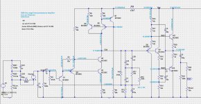
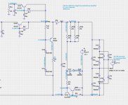
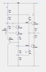
Looking at the schematic, it starts with a buffer (Q1) to isolate the transconductance stage (Q3) from the cartridge. There is a small noise penalty, but the alternative (no buffer) would load the cartridge too much, as Q3 runs at app 5mA.
Q2 and Q4 is a bootstrap for Q3 (*not* a cascode), increasing the output impedance of Q3, and all but removing any temperature drift of Q3.
Q5,6 and 7 forms a constant current source, which has to objectives:
1) making the combined output impedance of Q4, Q5, and Q6 very high, and 2) vastly improving the rejecting of power-line noise.
The reason for using two transistors (Q5, and Q6), is to lower the noise of R5/R6. With only one and half the emittor resistor would make more noise than R8. In this configuration it's actually lower.
R10, R11, R12, C3 and C4 forms the RIAA network.
R10, R13 and R2 together with C5 sets the DC operating point. The constant current generator mentioned earlier, defines the current that has to go through R8, which sets a well defined voltage (app 1V). In order to bias the input (Q1) correctly, the voltage over R13 will have to assume the same voltage and in order for this to happen, the voltage at the Q4's collector must assume the voltage 1V * (R10+R13)/R13 ~= 16.5V (I have not taken the difference in Vbe of Q1 and Q3 in account)
The output buffer is a more or less standard diamond configuration. I know it is a big gun to use here, but has a pretty good performance. It doesn't need much current to run, it has a very low distortion, and a very high input impedance. The latter is crucial in order for the RIAA network to work properly.
The combined impedance of Q4, Q5, Q6, Q8 and Q9 is close to 1.4MOhm (R10 should have been 200kOhm).
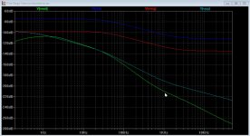
The PSU is not very fancy, but pretty good none the less. It is a shunt regulator,
It all starts with a 9V 1A wall-wart - no transformer in the enclosure.
Next is a voltage quadrupler giving app 50V, then follows a constant current source (Q101 and Q102) Ic =31mA. Then follows a low pass filter, and yes, I have not made an error: first C105, then R54. Finally an amplified Zener, and in order to remove the last bit of noise, a couple of low pass filters/Capacitor multipliers, one for each chanel.
So how does it sound ? Well, I'm not equipped with golden ears, but as far I can tell it is noise-free, no distortion that I can hear. All in all it's pretty good and I am rather pleased with it.
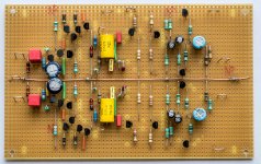
PS As you can tell from the board-picture, I don't do fancy PC-board work, but I try to make it look somewhat like the schematic - a great help when debugging.
So there you have it - any comments?
Lars
http://www.diyaudio.com/forums/analogue-source/255309-discrete-phono-stage-single-supply.html, and I posted a comment about the flaws I could see.
In any case, I started designing a MM preamp based on a transconductance amplifier, where one transistor was doing all the voltage amplifier work. Off course one transistor can't do it alone, so I ended up with a design that uses a little more. 11 tansistors in all per chanel, not counting the power-supply, but BJT transistors are fairly cheap...
I had one rule: only Capacitors, resitors, diodes, LEDs, and BJTs. No fancy components, no ICs. Why ? Because it's a challenge and it's fun, that's why!
Looking at the schematic, it starts with a buffer (Q1) to isolate the transconductance stage (Q3) from the cartridge. There is a small noise penalty, but the alternative (no buffer) would load the cartridge too much, as Q3 runs at app 5mA.
Q2 and Q4 is a bootstrap for Q3 (*not* a cascode), increasing the output impedance of Q3, and all but removing any temperature drift of Q3.
Q5,6 and 7 forms a constant current source, which has to objectives:
1) making the combined output impedance of Q4, Q5, and Q6 very high, and 2) vastly improving the rejecting of power-line noise.
The reason for using two transistors (Q5, and Q6), is to lower the noise of R5/R6. With only one and half the emittor resistor would make more noise than R8. In this configuration it's actually lower.
R10, R11, R12, C3 and C4 forms the RIAA network.
R10, R13 and R2 together with C5 sets the DC operating point. The constant current generator mentioned earlier, defines the current that has to go through R8, which sets a well defined voltage (app 1V). In order to bias the input (Q1) correctly, the voltage over R13 will have to assume the same voltage and in order for this to happen, the voltage at the Q4's collector must assume the voltage 1V * (R10+R13)/R13 ~= 16.5V (I have not taken the difference in Vbe of Q1 and Q3 in account)
The output buffer is a more or less standard diamond configuration. I know it is a big gun to use here, but has a pretty good performance. It doesn't need much current to run, it has a very low distortion, and a very high input impedance. The latter is crucial in order for the RIAA network to work properly.
The combined impedance of Q4, Q5, Q6, Q8 and Q9 is close to 1.4MOhm (R10 should have been 200kOhm).
The PSU is not very fancy, but pretty good none the less. It is a shunt regulator,
It all starts with a 9V 1A wall-wart - no transformer in the enclosure.
Next is a voltage quadrupler giving app 50V, then follows a constant current source (Q101 and Q102) Ic =31mA. Then follows a low pass filter, and yes, I have not made an error: first C105, then R54. Finally an amplified Zener, and in order to remove the last bit of noise, a couple of low pass filters/Capacitor multipliers, one for each chanel.
So how does it sound ? Well, I'm not equipped with golden ears, but as far I can tell it is noise-free, no distortion that I can hear. All in all it's pretty good and I am rather pleased with it.
PS As you can tell from the board-picture, I don't do fancy PC-board work, but I try to make it look somewhat like the schematic - a great help when debugging.
So there you have it - any comments?
Lars
Attachments
-
 One Stage Transconductance.jpg235.5 KB · Views: 290
 -
 OST - the board.jpg1 MB · Views: 158
 -
 OST - Power supply noise to Output.jpg171 KB · Views: 76
 -
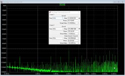
 OST - Noise.jpg125.9 KB · Views: 245
 -
 OST - Distortion.jpg205.5 KB · Views: 254
 -
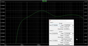 OST - AC analysis.jpg170.3 KB · Views: 268
 -
One Stage Transconductance.asc16.8 KB · Views: 38
-
 PSU One Stage Transconductance.jpg201.2 KB · Views: 288
Complex circuit. I can not decifer it completely on first sign. R2 ? Input Darlington works on a strange Cascode.
The bootstrapped Diamond Buffer is interesting. Does it also improve the unlinear input impedance of a standard Diamond Buffer ?
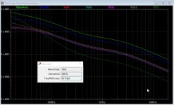
The distortion profile shows incredible lots of harmonics and intermodulation although on a low level. This is for an MM cartridge, right ?
The bootstrapped Diamond Buffer is interesting. Does it also improve the unlinear input impedance of a standard Diamond Buffer ?
The distortion profile shows incredible lots of harmonics and intermodulation although on a low level. This is for an MM cartridge, right ?
Hi,
nice circuit .... like it")
Interesting idea to use the Darlington Q1/2 ahead of Q3.
I wonder if You thought about using a CFP (Sziklai-pair) instead of Q3 .... and omit with Q1/2?
Could meet the requirement of high input impedance, especially as a hybrid-CFP in form of a JFET/bipolar combination.
The CFP might also generate less THD due to its high linearity .... and if a JFET with suitable Vgs is chosen You could omit with the input coupling cap and input biasing network alltogether.
jauu
Calvin
nice circuit .... like it
Interesting idea to use the Darlington Q1/2 ahead of Q3.
I wonder if You thought about using a CFP (Sziklai-pair) instead of Q3 .... and omit with Q1/2?
Could meet the requirement of high input impedance, especially as a hybrid-CFP in form of a JFET/bipolar combination.
The CFP might also generate less THD due to its high linearity .... and if a JFET with suitable Vgs is chosen You could omit with the input coupling cap and input biasing network alltogether.
jauu
Calvin
Bootstrap vs Cascode
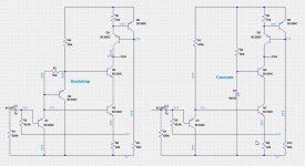
There is no darlington in the input. I have made a part-schematic, where I have rearranged the input slightly (the left part). You can remove Q2 and short emitter and collector of Q4 and you will have the same functionality. Well, not quite, as this will lower the output impedance.
The left circuit illustrates the principle of a bootstrap, i.e. to keep the voltage Vce of Q3 constant, thereby eliminating the outparameters of Q3. Q2 functions only as a levelshift for Q4.
The right circuit illustrates the principle of a cascode, which is to isolate the collector of Q3 from large voltage swings. Vce of Q3 will only see a change equal to the input voltage swing.
The difference is not that big, at least not here. I chose the bootstrap for three reasons: 1) Q2 doubles as both a bootstrap for Q1 and as a level shift for Q4, and 2) a zener adds noise and uses a lot of current app 10ma for a 3V Zener, which is more than the rest of the preamp! , and 3) For what its worth, I find it elegant.
Regarding rearranging the input: with a DC-gain of around 1000x you do need some form of control, otherwise the ouput voltage is anyones guess.
Lars
Attachments
Last edited:
The bootstrapped Diamond Buffer is interesting. Does it also improve the unlinear input impedance of a standard Diamond Buffer ?
The distortion profile shows incredible lots of harmonics and intermodulation although on a low level. This is for an MM cartridge, right ?
Yes it's for MMs.
The Diamond buffer: I haven't analysed it separately but I did try to look at the transient analysis before and after the buffer. I could not detect any difference, and I suspect you are correct. If you would design a better buffer with respect to linearity of the input, you could go down the road I have outlined in the attached schematic.
Q9 and Q10 have been added to bootstrap Q12 and Q7 respectively.
Q12 and Q7 now runs with constant current (due to the bootstrap with C4 and C5) and constant Vbe due to the new bootstrap. Haven't tried it though.
Lars
Attachments
- Status
- This old topic is closed. If you want to reopen this topic, contact a moderator using the "Report Post" button.