Hi guys!
I need your opinion about the type of power supply that the phono stage based on the OP TBA231 requires.
In an old thread of mine about this phono stage, some friend told me that it requires a symmetrical power supply.
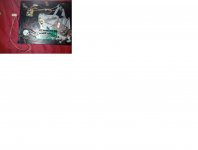
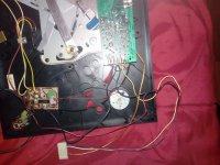
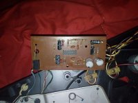
Anyway, I want to show you some pictures of this phono preamplifier and the strange connection between it and the motor speed control circuit board.
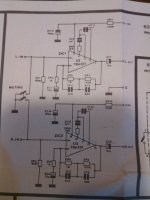
Please could you see the pictures (I add also the original Lesa phono stage schematic) and tell me if Ican use this pre-phono stage with a normal power supply or if it really requires a symmetrical power supply?
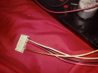
Just a note: please notice that the power supply cables welded on the phono stage board are two: one is white, the other one is black (this black cable is welded with another black cable that is connected to the motor speed control board).
Then, please notice that there's a not connected pin(the first one) on the prephono stage: I'm not sure (you know I'm a newbie) but this pin could be the third pole (I mean the "0" pin of the symmetrical power supply?) and as you can see it isn't connected to any cable.
I'm asking that, because I want to use this Lesa pre-phono stage in another turntable, so please let me know, what type of power supply I have to use, please guys!")
I need your precious help!
Thank you very much in advance for the patience and for your kindness, my friends!
Best regards from Italy
I need your opinion about the type of power supply that the phono stage based on the OP TBA231 requires.
In an old thread of mine about this phono stage, some friend told me that it requires a symmetrical power supply.
Anyway, I want to show you some pictures of this phono preamplifier and the strange connection between it and the motor speed control circuit board.
Please could you see the pictures (I add also the original Lesa phono stage schematic) and tell me if Ican use this pre-phono stage with a normal power supply or if it really requires a symmetrical power supply?
Just a note: please notice that the power supply cables welded on the phono stage board are two: one is white, the other one is black (this black cable is welded with another black cable that is connected to the motor speed control board).
Then, please notice that there's a not connected pin(the first one) on the prephono stage: I'm not sure (you know I'm a newbie) but this pin could be the third pole (I mean the "0" pin of the symmetrical power supply?) and as you can see it isn't connected to any cable.
I'm asking that, because I want to use this Lesa pre-phono stage in another turntable, so please let me know, what type of power supply I have to use, please guys!
I need your precious help!
Thank you very much in advance for the patience and for your kindness, my friends!
Best regards from Italy
Attachments
-
 lesa pre-phono with indications.jpg166.6 KB · Views: 227
 -
 lesa turntable with preamp RIIA.jpg84.2 KB · Views: 206
 -
 lesa turntable power and signal audio cable.jpg49.8 KB · Views: 205
 -
 lesa pre-phono RIIA with TBA231.jpg47.3 KB · Views: 217
 -
 lesa pre-phono RIIA with TBA231 frontal.jpg71.5 KB · Views: 233
 -
 TBA231.jpg47.5 KB · Views: 164
We answered this one some time ago
to get more gain: phono RIAA with TBA231 vs a simple SC12 H ceramic cartridge
to get more gain: phono RIAA with TBA231 vs a simple SC12 H ceramic cartridge
You need to be aware that the TBA231 is a true 'opamp' and it runs on dual or 'split' supplies consisting of a positive and a negative rail. It will not work (at least not without a redesign of the circuit) on a single 18 volt supply.
If you look carefully on the schematic, it shows -15V on lead #7 and +15V on lead #14 - pretty much standard for a SIL14 IC.
So a LM317L for the positive and an LM337L for negative. Look in the data-sheets for examples.
Lars
You're correct. Positive Negative 15VDC PSU. Picture not clear. My erroneous judgement, too used to 8pin DIL package opamps.
Better solution is the use of only one LM317 and two zeners like in use in the PP2 from NAD - go to second PDF in post #5 underIf you look carefully on the schematic, it shows -15V on lead #7 and +15V on lead #14 - pretty much standard for a SIL14 IC.
So a LM317L for the positive and an LM337L for negative. Look in the data-sheets for examples.
Lars
Head Pre for Denon DL 103
Hi guys!
just if you want to get the picture more bigger and clearer you have to click on the "X" that you can see in the bottom of the picture (in the left side)
That said, guys, please have mercy on me...I'm hust a newbie, unfortunately,
So, first of all, I'd like to ask a question to Mooly: Hi Mooly, in the previous thread you advised me how to use a normal power supply (I mean a not symmetrical power supply) on this phono stage based on the TBA231.
This is what you kindly suggested to me:
"The split rail supply is not necessarily an insurmountable problem. The opamp draws little current and so a simple method of obtaining a negative from the power supply could be an option.
If the mains transformer has a single secondary winding to generate the positive rail then the addition of a cap and a diode will generate an equal and opposite polarity rail. All you would then need would be either a negative regulator or a simpler resistor/zener shunt"
Well, my question is: now seeing the picture of this phono stage, coul you confirm that this circuitry doesn't need a symmetrical power supply?
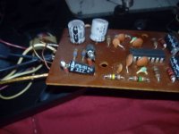
Moreover, in this phono stage, I've noticed two resistance welded to two electrolitycs capacitors: I apologize for my ignorance, but was this the way you talked about, in order to get a normal power supply instead of a simmetrycal one?
I repaeat: there's a pin (the first one on the phono stage) that is disconnected from any cable.
There're only two cables for the power supply connected to the pins of this phono stage, they're the black and the white cable.
That said, can't I use a normal and common power supply stage ( I mean a capacitor with a rectifier) connected with a 12 V transformer?
Please guys forgive me for my newbie questions.
Best regards
just if you want to get the picture more bigger and clearer you have to click on the "X" that you can see in the bottom of the picture (in the left side)
That said, guys, please have mercy on me...I'm hust a newbie, unfortunately,
So, first of all, I'd like to ask a question to Mooly
: Hi Mooly, in the previous thread you advised me how to use a normal power supply (I mean a not symmetrical power supply) on this phono stage based on the TBA231.This is what you kindly suggested to me:
"The split rail supply is not necessarily an insurmountable problem. The opamp draws little current and so a simple method of obtaining a negative from the power supply could be an option.
If the mains transformer has a single secondary winding to generate the positive rail then the addition of a cap and a diode will generate an equal and opposite polarity rail. All you would then need would be either a negative regulator or a simpler resistor/zener shunt"
Well, my question is: now seeing the picture of this phono stage, coul you confirm that this circuitry doesn't need a symmetrical power supply?
Moreover, in this phono stage, I've noticed two resistance welded to two electrolitycs capacitors: I apologize for my ignorance, but was this the way you talked about, in order to get a normal power supply instead of a simmetrycal one?
I repaeat: there's a pin (the first one on the phono stage) that is disconnected from any cable.
There're only two cables for the power supply connected to the pins of this phono stage, they're the black and the white cable.
That said, can't I use a normal and common power supply stage ( I mean a capacitor with a rectifier) connected with a 12 V transformer?
Please guys forgive me for my newbie questions.
Best regards
The cap with a 'welded' resistor is just a series cap and resistor, probably the feedback return cap (10uF) and the 1k resistor on the circuit diagram. Yours looks like a 2k2 resistor which would give a little less gain.
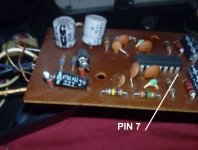
To determine if that board is configured for single rail you will have to see where the negative supply pin of the opamp goes. That looks like pin 7 of the diagram.
Further confirmation is to look at how the input is configured. If the input pin goes to ground via a single resistor (ZR1 and ZR2 in the diagram) then it is split rail.
If there is a resistor network to derive a half rail voltage then it is probably single rail.
If it goes to ground then it would seem the board is designed for single rail.
If it is configured as in the diagram then its a split supply.
The TBA231 was in use in the RIAA stage from follow vintage audio components from German's brand KS electronic (Kücke, Wuppertal):
1) Preamplifier V31 - go to
VORVERSTARKER KUCKE KS V-31 - EUR 123,00 | PicClick DE
Kucke KS V-31 Uberholung?
2) Receiver (FM Stereo Tuner & integrated amplifier) KS-digital
Schematics are not online, but still available here:
Kucke KS electronic | Hifi fur Anspruchsvolle
1) Preamplifier V31 - go to
VORVERSTARKER KUCKE KS V-31 - EUR 123,00 | PicClick DE
Kucke KS V-31 Uberholung?
2) Receiver (FM Stereo Tuner & integrated amplifier) KS-digital
Schematics are not online, but still available here:
Kucke KS electronic | Hifi fur Anspruchsvolle
Last edited:
Hi guys!
Here's a picture where I've drawed the rail starting from the pin N.7 of the TBA231.
I hope this can help you to establish definitively if this a symmetrical power supply design.
Hey dear Mooly, if you need other rails tracking, please let me know it...I'm here, of course!
Anyway, I apologize for this boring long question...I (a cursed newbie) but I need this information.
Anyway you can't imagine how much I appreciate your collaboration and I want to thank you all for this precious help.
Please guys, could you give me your definitive opinion?
Best regards
Here's a picture where I've drawed the rail starting from the pin N.7 of the TBA231.
I hope this can help you to establish definitively if this a symmetrical power supply design.
Hey dear Mooly, if you need other rails tracking, please let me know it...I'm here, of course!
Anyway, I apologize for this boring long question...I (a cursed newbie
) but I need this information.Anyway you can't imagine how much I appreciate your collaboration and I want to thank you all for this precious help.
Please guys, could you give me your definitive opinion?
Best regards
Attachments

Oh dear Mooly, you're absolutely right: I'm a big stupid
I hope you can forgive me...I'm driving you crazy and I'm very embarrassed for that.
You're a really kind and patient person: I want to thank you for all this support.
For me it's very important...unfortunately I'm having a bad time in my life (due to health problems) and this small project is helping me to forget my problems.
So thank you once again for all that you're doing to help me
That said, I was wrong to mark the pin, but everything else is correct here's the picture with the correction.
Mooly, please be patient: could you take a look at the picture with the correction and tell me if you need further informations to give me the final verdict about the power supply design?
Thank you and best regards from Italy, my friend!
Attachments
All you have to do is look where pin 7 goes on the board.
Does it go to the main ground traces on the board ? or does it connect directly (but possibly through a series resistor) to its own wire that feeds a supply into the board.
If the first option then it sounds like single rail, if the second option then most likely dual rail.
Does it go to the main ground traces on the board ? or does it connect directly (but possibly through a series resistor) to its own wire that feeds a supply into the board.
If the first option then it sounds like single rail, if the second option then most likely dual rail.
- Status
- This old topic is closed. If you want to reopen this topic, contact a moderator using the "Report Post" button.
- Home
- Source & Line
- Analogue Source
- vintage phono-pre based on TBA231: power supply type, see the pictures!