An interesting point. I think that cartridges represent a sort of "boutique" business model. Perhaps not so much for the pre. There was some significant research done on cartridge/preamp interaction, with the result being a preamp with very little interaction with the cartridge. I've wondered since that patent expired why nobody else ever did it.That's certainly true, and in fact I've wondered why no one ever made (at least to my knowledge) a cartridge/preamp combination which was designed together to provide accurate RIAA.
I like to solve the big issues that are unmistakably audible first. Some of those are huge, and not easy to solve. The tiny possibly inaudible ones tend to tickle my OCD, but I usually resist and focus on the practical. But everyone has their pet projects.I don't think anyone here is oblivious to the fact that cartridges typically exhibit far greater errors in freq response than any half decent preamp. But that doesn't mean playing around with this preamp has been an exercise in futility, I've learnt quite a bit doing it which is sort of the point.
Well, my only brief comment would be, if performance changes with power supply voltage change, and stock is not optimum, we have a poor design, and an opportunity for modification. Second comment would be...ABX...ABX...ABX before putting much stock in subjective judgements.Btw. I tested the preamp with different power supplies and like simulated, supply voltage does affect the low end response and that bump flattens away when used with 12V voltage like it was designed for. But to my ears higher voltage sounds better and it does lower THD. Now I'm a bit unsure which I'm hearing more, the difference in response or the lower THD. It's hard to tell, since the difference is subtle and I'd say more in the high frequencies, but playing around with this thing I've noticed just because you change response in some parts, doesn't mean that's where you perceive the change to be.
What sort if attenuation networks are being used? Would you want something that doesn't load the sound card output to much, but still has approximately the output impedance of a phono cart?
I did think about that, and elected to go with a simple L attenuator. The preamp sees a source Z much lower than a cartridge, but since the preamp is technically not supposed to be a reactive load (yeah, I know, most are a little), it's not really a problem. Clearly, the ART preamp I tested works just fine with a relatively low source Z.
Noise should be measured with a typical cartridge source Z termination, though. The problem is, they're all different! Even though they "expect" 47K/200pf, they all source differently, so what do you use?
I get back to the fact that the preamp alone doesn't tell you much. Clearly, even the cheap stuff hits the ideal curve quite well. However, cartridges have issues and interact with preamps. That's really where the work needs to be.
Now, think of this: If you had some random cartridge, and could do a precision response test on in through a preamp of choice, you could follow that with a DSP EQ and flatten the thing out perfectly. The process could even be semi-automated, and get you pretty much spot-on. Just a thought.
When I ran digital crossovers and EQ, I ran my phono preamp into an ADC then into the system. That allowed for a phono preset where EQ and balance of the cartridge were taken care of. IIRC, that worked fairly well.
From poking around the web, it seems that the output impedance of most MM carts in in the 1K-2K range. MC much lower, of course. Does anyone here know? Does it matter?
From poking around the web, it seems that the output impedance of most MM carts in in the 1K-2K range. MC much lower, of course. Does anyone here know? Does it matter?
There are preamps that are specifically designed for one type of moving-magnet cartridge, such as this one:
Linear Audio | your tech audio resource
I don't remember how accurate the response was.
Yeah, that idea sparked off two threads of debate. We are still not sure Steven's model is correct. 13dB of resonant gain at 20kHz seems unbelievable esp when MCs with same cantilever and diamond, just different damping are flat. We are still trying to work out how to get to the bottom of what is electrical and what is mechanical. For fun
")
I have miniDSP so am slowly evolving to a flat preamp and digital RIAA with corrections as required. But still need a calibrated test record...
When I ran digital crossovers and EQ, I ran my phono preamp into an ADC then into the system. That allowed for a phono preset where EQ and balance of the cartridge were taken care of. IIRC, that worked fairly well.
From poking around the web, it seems that the output impedance of most MM carts in in the 1K-2K range. MC much lower, of course. Does anyone here know? Does it matter?
I believe I saw cart impedances from 33K and down to 2K, but others may have better data.
Cartridge source Z is definitely one part of cartridge/preamp interaction that affects the output FR, but it's not the only part, and is very cartridge specific.
It's a slight issue when testing a preamp, but there's not much point in replicating a cartridge source Z because it's a complex electrical model, and there are other things going on in the cartridge anyway. A lot of effort could be expended to create a rather inaccurate model of a cartridge source Z, and testing that way would still not accurately predict the real result of a cartridge working into a preamp.
This is why just testing a preamp for RIAA match is just an exercise. Apart from how the preamp loads the cart, there are several other possible interactions that are very difficult to simulate, and change with each cartridge. All we can practically do is test the pre for RIAA match, and realize that's NOT going to be what happens at the output with an actual cartridge. Then test the total system, and react to that result.
From poking around the web, it seems that the output impedance of most MM carts in in the 1K-2K range. MC much lower, of course. Does anyone here know? Does it matter?
1 kohm is the right order of magnitude for MM at low frequencies, but with an inductance of the order of 500 mH, the impedance at 20 kHz will be much higher.
The conventional way to make an amplifier that works with any MM cartridge is:
A. Make sure that it accurately follows the RIAA curve when driven from a low impedance
B. Make sure its input impedance is equivalent to 47 kohm in parallel with a controllable capacitance
C. Noise-optimize it for a typical MM cartridge impedance, say 1 kohm in series with 500 mH
The cartridge manufacturer should then take care of the resonance of the cartridge impedance with its load. Usually cartridge manufacturers adjust this resonance and the mechanical resonance of the stylus and magnet such that together they more or less approximate a flat response from stylus velocity to loaded cartridge output voltage.
If you don't require the amplifier to work with any MM cartridge, you can try tricks like Hans van Maanen and Steven van Raalte use: relatively low resistance load to get rid of the electrical resonance plus a correction filter for the mechanical resonance.
Marcel: Until I tripped over the tests on Transimpedance amplifiers I was seriously considering the 'damped RIAA' approach (I prefer Bob Cordell's nomenclature). Bob went one better with cooled loading to remove the noise penalty of rolling off at 2kHz.
However I still don't buy Steven's mechanical resonance calculations. But onus is I realise on me to measure that
However I still don't buy Steven's mechanical resonance calculations. But onus is I realise on me to measure that
Bill,Bob went one better with cooled loading to remove the noise penalty of rolling off at 2kHz.
The somewhat complicated trick with a "cooled" input resistor can lower the noise, but don't expect miracles, it will be in the order of 1 a 2 dB max as can be easily proven by simulation.
So this marginal improvement will only extend S/N beyond the "more than enough" that is achievable with modern OPA's.
Hans
Marcel: Until I tripped over the tests on Transimpedance amplifiers I was seriously considering the 'damped RIAA' approach (I prefer Bob Cordell's nomenclature). Bob went one better with cooled loading to remove the noise penalty of rolling off at 2kHz.
However I still don't buy Steven's mechanical resonance calculations. But onus is I realise on me to measure that
Frankly I don't understand Bob Cordell's damped version. If you have a fourth-order Chebyshev low-pass with the most complex pole pair made by a mechanical resonance and the least complex pole pair made by an electrical resonance, only removing the electrical resonance without doing anything about the mechanical resonance should give you a response with a significant peak at the mechanical resonant frequency.
I didn't know Bob Cordell actually built a version with electronic cooling (electronic cooling is what W. S. Percival and W. L. Horwood named it back in 1939, see W. S. Percival, "An electrically "cold" resistance", The wireless engineer, vol. 16, May 1939, pages 237...240). I remember having an e-mail discussion with Bob Cordell about it and in the end agreeing that electronic cooling should help a few dB.
Yes Bob Quotes you here http://www.cordellaudio.com/preamplifiers/vinyltrak.shtml
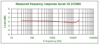
Let me dig out the measurement of an OM40 with transimpedance loading (150Ohms). Not much resonance there. We have some threads discussing this in particular so as to not throw this one too far off track.
Let me dig out the measurement of an OM40 with transimpedance loading (150Ohms). Not much resonance there. We have some threads discussing this in particular so as to not throw this one too far off track.
Attachments
Last edited:
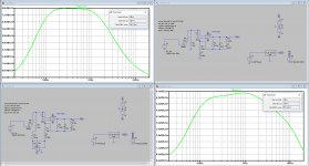
Here is an example of two versions build with the OPA1652, a state of the art Fet OPA in combo with a 500 mH / 600 Ohm cart,
One is with "Cooled Resistor", the other one isn't.
Difference in S/N between the two: 20*log(436/531) = 1.7 dBA.
(The same done with the OPA1642 gives 20*log(472/549) = 1.3 dBA).
S/N with OPA1655 referred to 5mV@1Khz is 79,4dBA and with"cooling" 81,2dBA, including the Cart !
Technically most interesting, but practically beyond what is needed IMHO.
Hans
Attachments
So it seems, I was just triggered by the word "cooled".Ah, apples to grapefruits. The 2.4dB is when you are loading to get a 2kHz pole, your example appears to be a synthetic 47k load? I think we are in violent agreement here
I'll have a look at Bob's article in LA4.
Hans
For the 47 kohm case, you could improve it a bit further by either using an ultra low noise op-amp for the inverting amplifier, or completely separating the cold resistor circuit from the RIAA amplifier using three FET op-amps. That saves you the 4.5 nV/sqrt(Hz) voltage noise penalty that the bottom op-amp gives you.
On the other hand, the implicit assumption that the ESR of a moving-magnet cartridge is constant is incorrect, it increases substantially across the audio band (or at least it did on the cartridge that a friend of mine measured in the 1990's). That increases the cartridge's thermal noise and reduces the possible improvement. I once calculated a best-case improvement of about 3 dB(A) for an otherwise noiseless RIAA amplifier connected to the cartridge that that friend of mine measured, all assuming only thermal noise and no record surface noise.
In any case, an improvement of 1.7 dB(A) or 3 dB(A) or whatever it may be may well be audible when you don't play a record and turn the volume up high, so its practical significance is much greater than that of reducing the distortion of an audio power amplifier from 0.01 % to 0.0001 %.
Last edited:
If you would take an ultra low noise version for the inverting amp, you could just as well take a main amp that has lower noise than the OPA1652 having 3.8nV/rtHz.
So I still don't see the advantage of using this "cool"circuit and I also fail to see a reason for having a Riaa amp with a S/N of 80dBA or more.
There is just another more simple reason against using it.
The dBA figures are giving the impression that the noise is lowered.
As a sum over the whole spectrum this is true, but the spectra have different shapes with more noise in the mid sector when displayed on a 1/3 octave base and less above 10KHz for the cooled version.
When using ITUR weighting, more reflecting to what you hear, the differences become much smaller.
Hans
According to my calculations, optimizing the RIAA- and A-weighted noise is essentially equivalent to optimizing the spot noise at 3852 Hz, while optimizing the RIAA- and ITU-R-weighted noise is essentially equivalent to optimizing the spot noise at 5179 Hz (assuming white and uncorrelated input noise current and voltage and modelling the cartridge impedance with an LR series network). As a cartridge has a higher impedance at 5179 Hz than at 3852 Hz, the noise current you can eliminate with an electrically cold resistance should have more impact with ITU-R 468 weighting.
If you would take an ultra low noise version for the inverting amp, you could just as well take a main amp that has lower noise than the OPA1652 having 3.8nV/rtHz.
Of course you can, as long as it's not an ultra low voltage noise, ultra high current noise op-amp (like most bipolar op-amps with base current compensation: LT1028, AD797 and the like). The inverting amp is far less sensitive to current noise.
- Status
- This old topic is closed. If you want to reopen this topic, contact a moderator using the "Report Post" button.
- Home
- Source & Line
- Analogue Source
- Measuring phono stage RIAA accuracy with a computer