Those dimensions sound about right for the magnet I was working with. As I said, it works fine now and I’m happy.
@Super...Sounds like you’re from the same area upstate I used to visit a lot when I was a kid. We had relatives from Pleasantville all the way up past Brewster. I will definitely keep in touch if I get involved in an air bearing arm. I spent countless hours in the thread devoted to them on here and other resources related to the Ladegaard experiments taking notes.
@Super...Sounds like you’re from the same area upstate I used to visit a lot when I was a kid. We had relatives from Pleasantville all the way up past Brewster. I will definitely keep in touch if I get involved in an air bearing arm. I spent countless hours in the thread devoted to them on here and other resources related to the Ladegaard experiments taking notes.
I will definitely keep in touch if I get involved in an air bearing arm. I spent countless hours in the thread devoted to them on here and other resources related to the Ladegaard experiments taking notes.
I am not too crazy about Ladegaard's style air bearing arm personally. I would highly recommend to build a New Way air bushing style air bearing arm. High pressure air is a problem for many people so I have experimented low air pressure for my arm. My arm can run under air pressure as low as 7 psi. The arm sounded somewhat to loose dynamics comparing with high pressure, but it still sounded very very good. It is another topic. When time comes, we will talk again.
With the skills and capacity you have, I believe you can make a very nice air bearing arm.
I think I’ve gone over all the major aspects of fabrication for the project. Final set up of the table had some pitfalls.
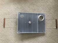
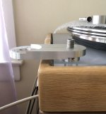
Actually, even before I got to final set up I needed to be able to fit the plinth into the base to test clearance, height etc. I knew the plinth was quite heavy and I would need a way to hold it firmly while lowering it in place on the suspension. My first attempt was some handles that had hooks on the end and were covered with rubber tubing. They were supposed to grab the edge of the folded steel sub-chassis to help me hold and lower it in place and then pull out of the gap around the plinth.
The handles didn’t work. Actually, I ended up dropping the heavy plinth from about an inch above onto the base and damaged the oak on one of the inner edges at the top of the base. That’s why its now beveled. My plan B was two sections of copper tubing with some tough nylon string to cradle the plinth from below. It supports the plinth properly, is stable and is easily removable by using the arm board hole as a grip to slightly lift the plinth and snake the string out. I have left it in place for now in case I find I need to change something during my testing period.
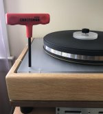
The rest of the set up went smoothly. I leveled the table easily using a T handle Allen wrench from above with my new suspension design. Routing of the wiring for the controller was also easy because I only had one power source. The sensor and motor cable was easily routed as well and everything looked tidy. The tonearm was a breeze to set up. The new removable arm board made it much easier to adjust the the VTF setting of the arm to the height of the new thicker platter. I went back over the cartridge alignment, tracking force etc.
When I first set the table up I decided to test it via rim drive. This was mainly due to my experiments in the shop with the black VPI drive belts. They appeared to slip a lot and cause speed instability. There was no good reason for that as the dimensions of the table were the same and if anything there should have been more tension on the belts due to the slightly larger platter.
In hindsight, I now realize that the slippage issue may have been due to the fact that my “Super Platter” did not come with grooves machined in it for the belts. That would definitely reduce the contact area between the belts and platter and affect grip and stability. The black belts wanted to dance around on the edge of the platter. I remember contacting Harry at VPI years ago when I received the platter and asking why there were no grooves. He said they were having too many issues with loosing platters during the machining process of the grooves due to chipping. The trade-off is that I have an ideal surface to use a rim drive.
The table worked great with the rim drive. Unfortunately, there was one drawback. It was due I think to the slight imperfections in either the O-rings I was using to make contact between the motor pulley and the platter or the fact that my pulley wasn’t perfectly concentric enough, or both.
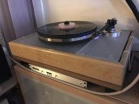
I was getting a resonance that was being amplified by the hollow walls of the IKEA bookcase I have hung on the wall that my table sits on. I tried minimizing it by adjusting the distance of the motor and platter so that it made just enough contact to maintain stable speed. It did improve things, but ultimately the resonance was still there and I was focused on it. It was being transferred down through the motor pod and into the cabinet. If I opened a door on the cabinet it would get very faint.
I couldn’t put anything under the motor to dampen the resonance because the clearance under the plinth was minimal to get a proper alignment with the pulley and platter. I rechecked the pulley and it barely measured movement on my .001 dial gauge when mounted on the motor and spinning. Perhaps using only one O-ring to engage the platter may have reduced the resonance, but then I suspect I may have started having issues with speed stability again. I will have to experiment more in the future, perhaps I need a different shelf that can absorb and dampen things better.
In the mean time I decided to try belt drive again. However, this time I used the original clear style VPI drive belt that came with my HW19. It is slightly shorter than the black belts and appears to be made of a slightly stickier rubber compound. I use all 3 belts with the clear one in the center. All the belts appear stable on the platter this way and there is excellent speed stability. There is no audible noise at all coming from the drive system this way.
There is a definite “warm up” period for the drive system. I don’t know exactly what factors cause it, but the speed wants to very slowly creep up over a 30 minute or so time period. This is being measured in thousands by the RoadRunner. Perhaps it is friction on the belts, lubrication in the motor, performance of components in the control circuit under different temperature or all of the above. I have tried to set a compensation into the frequency that drives the motor so that if I wait ten minutes or so after starting the table the speed has already climbed to within an acceptable tolerance (acceptable based on my mood). It is easy to compensate by adjusting the frequency by .01 if I’m feeling impatient and anal and then just wait to reduce it after I’ve played a side or two.
Actually, even before I got to final set up I needed to be able to fit the plinth into the base to test clearance, height etc. I knew the plinth was quite heavy and I would need a way to hold it firmly while lowering it in place on the suspension. My first attempt was some handles that had hooks on the end and were covered with rubber tubing. They were supposed to grab the edge of the folded steel sub-chassis to help me hold and lower it in place and then pull out of the gap around the plinth.
The handles didn’t work. Actually, I ended up dropping the heavy plinth from about an inch above onto the base and damaged the oak on one of the inner edges at the top of the base. That’s why its now beveled. My plan B was two sections of copper tubing with some tough nylon string to cradle the plinth from below. It supports the plinth properly, is stable and is easily removable by using the arm board hole as a grip to slightly lift the plinth and snake the string out. I have left it in place for now in case I find I need to change something during my testing period.
The rest of the set up went smoothly. I leveled the table easily using a T handle Allen wrench from above with my new suspension design. Routing of the wiring for the controller was also easy because I only had one power source. The sensor and motor cable was easily routed as well and everything looked tidy. The tonearm was a breeze to set up. The new removable arm board made it much easier to adjust the the VTF setting of the arm to the height of the new thicker platter. I went back over the cartridge alignment, tracking force etc.
When I first set the table up I decided to test it via rim drive. This was mainly due to my experiments in the shop with the black VPI drive belts. They appeared to slip a lot and cause speed instability. There was no good reason for that as the dimensions of the table were the same and if anything there should have been more tension on the belts due to the slightly larger platter.
In hindsight, I now realize that the slippage issue may have been due to the fact that my “Super Platter” did not come with grooves machined in it for the belts. That would definitely reduce the contact area between the belts and platter and affect grip and stability. The black belts wanted to dance around on the edge of the platter. I remember contacting Harry at VPI years ago when I received the platter and asking why there were no grooves. He said they were having too many issues with loosing platters during the machining process of the grooves due to chipping. The trade-off is that I have an ideal surface to use a rim drive.
The table worked great with the rim drive. Unfortunately, there was one drawback. It was due I think to the slight imperfections in either the O-rings I was using to make contact between the motor pulley and the platter or the fact that my pulley wasn’t perfectly concentric enough, or both.
I was getting a resonance that was being amplified by the hollow walls of the IKEA bookcase I have hung on the wall that my table sits on. I tried minimizing it by adjusting the distance of the motor and platter so that it made just enough contact to maintain stable speed. It did improve things, but ultimately the resonance was still there and I was focused on it. It was being transferred down through the motor pod and into the cabinet. If I opened a door on the cabinet it would get very faint.
I couldn’t put anything under the motor to dampen the resonance because the clearance under the plinth was minimal to get a proper alignment with the pulley and platter. I rechecked the pulley and it barely measured movement on my .001 dial gauge when mounted on the motor and spinning. Perhaps using only one O-ring to engage the platter may have reduced the resonance, but then I suspect I may have started having issues with speed stability again. I will have to experiment more in the future, perhaps I need a different shelf that can absorb and dampen things better.
In the mean time I decided to try belt drive again. However, this time I used the original clear style VPI drive belt that came with my HW19. It is slightly shorter than the black belts and appears to be made of a slightly stickier rubber compound. I use all 3 belts with the clear one in the center. All the belts appear stable on the platter this way and there is excellent speed stability. There is no audible noise at all coming from the drive system this way.
There is a definite “warm up” period for the drive system. I don’t know exactly what factors cause it, but the speed wants to very slowly creep up over a 30 minute or so time period. This is being measured in thousands by the RoadRunner. Perhaps it is friction on the belts, lubrication in the motor, performance of components in the control circuit under different temperature or all of the above. I have tried to set a compensation into the frequency that drives the motor so that if I wait ten minutes or so after starting the table the speed has already climbed to within an acceptable tolerance (acceptable based on my mood). It is easy to compensate by adjusting the frequency by .01 if I’m feeling impatient and anal and then just wait to reduce it after I’ve played a side or two.
Attachments
-
 AFA2CBF7-35D8-4857-93B4-9726802EBC20.jpg1.1 MB · Views: 374
 -
 8B8EAEFF-1003-4270-947C-25C8E9B4E44A.jpg481.9 KB · Views: 366
 -
 0FF732A2-3323-4476-84C9-AAAB2A2D2167.jpg841 KB · Views: 376
 -
 6FAFD896-E32F-45A5-A260-48205353D598.jpg815.2 KB · Views: 361
 -
 B0702C31-5F35-40BF-B75F-3FC9F8518D9D.jpg734.3 KB · Views: 364
Last edited:
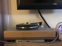
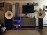
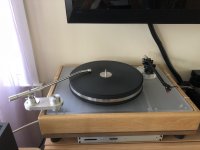
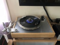
I'm perplexed as to why you have the monstrously heavy turntable on a piece of flimsy Ikea furniture instead of that beautiful, sturdy Flexy rack right next to it! I get wanting to have your RCM at a lower height for easier use, but why on earth would you want it that close to your audio gear, and on a rack so clearly ideal for your turntable!? I also do question the choice of feet for the lower part of your plinth. Either extra-firm Tenderfeet or spikes would probably be better there. And why don't you have a platform between the lower half of the plinth and the cabinet, like you have for everything on the beautiful Flexy rack? Everything else you have done here looks so well thought out, but your most vibration-prone components (tube amp, turntable) are still missing the most common tweak!
On the subject of belts, have you considered trying a flat belt? While your pulley does have grooves, a flat belt might reduce/eliminate the drift issue that you describe here since the pulley is single-speed anyway. Or you could make another pulley without grooves.
On the subject of belts, have you considered trying a flat belt? While your pulley does have grooves, a flat belt might reduce/eliminate the drift issue that you describe here since the pulley is single-speed anyway. Or you could make another pulley without grooves.
Last edited:
On the subject of belts, have you considered trying a flat belt? While your pulley does have grooves, since it's single-speed anyway, it would reduce/eliminate the drift issue that you describe here.
In order to use a flat belt, the motor will need a crowned pulley, otherwise the belt will migrate up or down and fall off the pulley.
The speed drift chromenuts observed is fairly typical and is the reason why I created the feedback loop between the PSU and the tach. I initially created the tach to measure the PSU performance, but no matter how accurately I set the speed initially, it would always drift upwards over 30-45 minutes. The tach had a serial output (initially USB), that was intended for logging the speed readout on a computer. The solution became obvious once the symptom appeared: connected the serial output of the tach to the PSU to compensate the drift in speed.
There are no changes in the electronics causing the speed drift, it is purely mechanical (bearing oil viscosity, belt diameter and Young's modulus changes with time/heat). While the motor RPM is constant with time, the platter speed will vary with small changes in drag manifested as belt creep. Unlike belt slippage which can be cured with correct tension, belt creep cannot be cured, it is an unintended byproduct of torque. It can however, be compensated for with feedback, and if done correctly, is inaudible.
@Packgrog
It’s all about circumstance. Everything you see is in flux. The “flexy” rack as you describe it is nothing more than one of my experiments that didn’t turn out the way I had hoped. It is in fact flexible...and not the way I would want it to be in terms of being able to reset shelf height as is required. I made it from materials I had lying around because I was running out of space. It is some 3/8” stainless rod and MDF. There aren’t any isolation platforms. There are just some cross braces glued and screwed to the bottom of the MDF shelves to reinforce them. I wanted some more space quickly and it wasn’t well thought out. It actually sways easily side to side because the 3/8” rod is too “flexy”.
Until now the IKEA shelf that I hung and anchored directly into my wall studs to isolate it from the floor vibration from footfalls or otherwise has actually worked very well. I often put music on for my kids and my daughter is a very enthusiastic dancer. Never had a skip.
I agree that there needs to be some kind of damping platform under the table if I want to continue to experiment with the rim drive option. I’m not a huge fan of cone feet, and actually got rid of the cone feet that were originally on the table. I think once the table is in its permanent home it will be fine.
My hobby has outgrown the space limitations of my living room and I have been unhappy with the situation for a while. I am in the process of planning my biggest audio project ever which will be tearing down an old sunroom on the back of my house and rebuilding it with the priority of having a better listening space.
@Pyramid
I suspected the creep was part of the reason for the feedback feature between the RoadRunner and Falcon you developed. Obviously the Falcon was a dead end for me personally because I wanted to use a motor that was beyond what it was originally designed for.
The SG4/M3D project has been a dream come true and really was the reason I even considered going forward with this project. Thank you for that. If there was a way to take advantage of feedback from the RoadRunner with the SG4 I would probably go for it. However, its not something I can’t live without either.
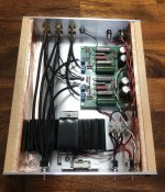
P.S. No tube gear running in that pic...just my stereo Gainclone project that I fabricated so the transformer was outside the case and had a cover.
It’s all about circumstance. Everything you see is in flux. The “flexy” rack as you describe it is nothing more than one of my experiments that didn’t turn out the way I had hoped. It is in fact flexible...and not the way I would want it to be in terms of being able to reset shelf height as is required. I made it from materials I had lying around because I was running out of space. It is some 3/8” stainless rod and MDF. There aren’t any isolation platforms. There are just some cross braces glued and screwed to the bottom of the MDF shelves to reinforce them. I wanted some more space quickly and it wasn’t well thought out. It actually sways easily side to side because the 3/8” rod is too “flexy”.
Until now the IKEA shelf that I hung and anchored directly into my wall studs to isolate it from the floor vibration from footfalls or otherwise has actually worked very well. I often put music on for my kids and my daughter is a very enthusiastic dancer. Never had a skip.
I agree that there needs to be some kind of damping platform under the table if I want to continue to experiment with the rim drive option. I’m not a huge fan of cone feet, and actually got rid of the cone feet that were originally on the table. I think once the table is in its permanent home it will be fine.
My hobby has outgrown the space limitations of my living room and I have been unhappy with the situation for a while. I am in the process of planning my biggest audio project ever which will be tearing down an old sunroom on the back of my house and rebuilding it with the priority of having a better listening space.
@Pyramid
I suspected the creep was part of the reason for the feedback feature between the RoadRunner and Falcon you developed. Obviously the Falcon was a dead end for me personally because I wanted to use a motor that was beyond what it was originally designed for.
The SG4/M3D project has been a dream come true and really was the reason I even considered going forward with this project. Thank you for that. If there was a way to take advantage of feedback from the RoadRunner with the SG4 I would probably go for it. However, its not something I can’t live without either.
P.S. No tube gear running in that pic...just my stereo Gainclone project that I fabricated so the transformer was outside the case and had a cover.
Last edited:
The SG4/M3D project has been a dream come true and really was the reason I even considered going forward with this project. Thank you for that. If there was a way to take advantage of feedback from the RoadRunner with the SG4 I would probably go for it. However, its not something I can’t live without either.
I second on what you said and all cheers to Bill. At the back of my mind, was hoping Bill or someone else can invent another tt platter feedback thing to connect to the SG4 for speed control. Hope I described it right.
More Basterdization...
So I have been wanting to try MC carts for years now...pretty much ever since I got back into audio and started building my own equipment.
Several years ago I bought a Denon 103 which might be considered the MC virgin’s cart. Only after the purchase did I begin to become aware of the issues that were involved with using the Denon in my system.
I didn’t have enough gain in my preamp which was designed for MM. The tonearm I was using was not a good match for the low compliance of the 103...etc...etc.
Somewhere along the line I came across a ZYX headamp and had enough money burning a hole in my pocket. I still didn’t have what I considered to be an appropriate tonearm, and it was just too easy to sit back and continue using my MM setup.
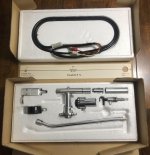
This past year around Xmas I came across an old 12” Stax UA3 tonearm that was listed on the USAudio Mart and eBay. It seemed reasonably priced compared to other long high mass tonearms I had been looking at. I mentioned it to my wife and was lucky enough to find it under the tree.
Unfortunately, the seller pulled a fast one and used different pictures for the listing on eBay which did not include the lift mechanism, its platform or the retro fitted anti-skate mechanism that was pictured on USAudio. I was kind of pissed, and when I contacted him about it all he did was to try and sell me the bits at substantial extra cost. I decided not to give him any more of my money.
Over the past few months I’ve been working out how to get everything I need together to finally try out the Denon and a few other MCs I collected on my recently bastardized HW19.
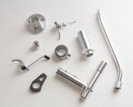
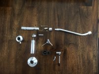
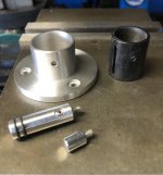
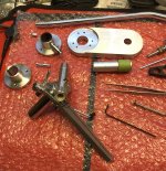
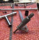
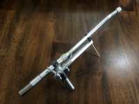
Here’s a pic of what I actually had to work with and some of the early work on the arm board system I came up with to add it to my table. Things got a bit more complicated as they moved along and I got it in my head that I was going to fabricate my own lift, anti-skate and adjustable VTA systems...well kind of.
Everything was fabricated with an inexpensive Grizzly Mini Mill and an old Logan lathe I got off of Craigslist a few years back.
So I have been wanting to try MC carts for years now...pretty much ever since I got back into audio and started building my own equipment.
Several years ago I bought a Denon 103 which might be considered the MC virgin’s cart. Only after the purchase did I begin to become aware of the issues that were involved with using the Denon in my system.
I didn’t have enough gain in my preamp which was designed for MM. The tonearm I was using was not a good match for the low compliance of the 103...etc...etc.
Somewhere along the line I came across a ZYX headamp and had enough money burning a hole in my pocket. I still didn’t have what I considered to be an appropriate tonearm, and it was just too easy to sit back and continue using my MM setup.
This past year around Xmas I came across an old 12” Stax UA3 tonearm that was listed on the USAudio Mart and eBay. It seemed reasonably priced compared to other long high mass tonearms I had been looking at. I mentioned it to my wife and was lucky enough to find it under the tree.
Unfortunately, the seller pulled a fast one and used different pictures for the listing on eBay which did not include the lift mechanism, its platform or the retro fitted anti-skate mechanism that was pictured on USAudio. I was kind of pissed, and when I contacted him about it all he did was to try and sell me the bits at substantial extra cost. I decided not to give him any more of my money.
Over the past few months I’ve been working out how to get everything I need together to finally try out the Denon and a few other MCs I collected on my recently bastardized HW19.
Here’s a pic of what I actually had to work with and some of the early work on the arm board system I came up with to add it to my table. Things got a bit more complicated as they moved along and I got it in my head that I was going to fabricate my own lift, anti-skate and adjustable VTA systems...well kind of.
Everything was fabricated with an inexpensive Grizzly Mini Mill and an old Logan lathe I got off of Craigslist a few years back.
Attachments
-
 FC4FB516-8E9F-4263-9F5B-A0F54818E7B2.jpg636 KB · Views: 230
 -
 F396261B-AC2B-49B4-9C67-A59479BD41A5.jpg513.4 KB · Views: 175
 -
 31937CE3-324B-4CA8-A984-8B00A6A2557E.jpg455.2 KB · Views: 156
 -
 406A7C06-4E85-410C-9875-08A2C6A28CB8.jpg417.6 KB · Views: 166
 -
 3714BBC3-772A-46BF-8026-1A4BBD174EFF.jpg838.1 KB · Views: 190
Last edited:
Thanks very much for the nice words.
@KevinKR
I actually have the arm set up well enough with the 103 to play now and I am very pleased so far with the results. It is not optimized, but I’ll work on it as I can. I am not very good at documenting and posting while I work, so I tend to do that when I find some time toward the end of the project. It makes it a little difficult to remember the order of events when things get complicated (always).
@AVWERK
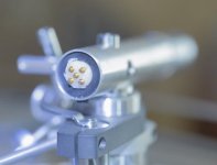
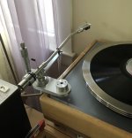
Adding an LED is actually an interesting idea as I have difficulty cueing with this arm due to its reverse position on the table and the fact that the TV is hung on the wall above with no light nearby. I was thinking of trying to hang a light somewhere on the back wall, but wasn’t sure about room and aesthetics. I wonder if I mounted a white LED close to the back corner of the plinth if I’d get enough illumination to help.
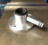
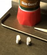
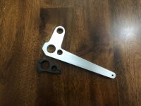
After getting the new arm board set up and adjusting its mounting height with a bit of fly cutting I started thinking about needing the tonearm lift. How was I going to mount it? What would I do about anti-skate and adjustable VTA?
I had a couple of Rega tonearm lifts I had purchased for tonearm projects. I had seen the stock Stax UA7 plastic lift mounts and how they tied in the mechanical anti-skate. I wasn’t sure if I should build an add on arm and just use monofilament and a weight for anti-skate instead.
Some things seem to be decided for us. I was researching the Stax anti-skate arrangement online and came across a damaged Stax UA7 tonearm on eBay for about $100. The lift mount and bayonet mount for the tonearm to the bearing housing were damaged. Perhaps in an effort to fix a short or something.
I knew I was going to build my own lift mount at this point anyway because I wanted to use it to integrate the VTA adjustment as well. All the important bits were there so I bought the UA7 for parts, and for a lot less than what the original seller of my tonearm was trying to rake me over the coals for.
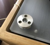
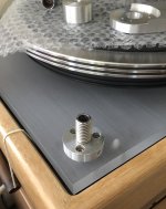
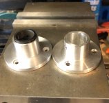
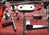
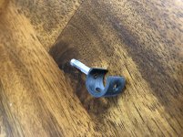
So at this point I started by tearing down the damaged arm to harvest the parts I needed (learned a lot from that). I also decided how I was going to make the base for the arm adjustable and ordered some inexpensive micrometer heads on eBay. First step was to create a Delrin bushing system for the base to bearing housing junction.
Here’s a few pics of what I got with the damaged parts arm (including the listing pics). The tear down and the bits for the base. The bushing system. Ultimately I couldn’t use the reworked lockdown fastener as it interfered with mounting the anti-skate. Instead I made my own nylon padded grub screws.
@KevinKR
I actually have the arm set up well enough with the 103 to play now and I am very pleased so far with the results. It is not optimized, but I’ll work on it as I can. I am not very good at documenting and posting while I work, so I tend to do that when I find some time toward the end of the project. It makes it a little difficult to remember the order of events when things get complicated (always).
@AVWERK
Adding an LED is actually an interesting idea as I have difficulty cueing with this arm due to its reverse position on the table and the fact that the TV is hung on the wall above with no light nearby. I was thinking of trying to hang a light somewhere on the back wall, but wasn’t sure about room and aesthetics. I wonder if I mounted a white LED close to the back corner of the plinth if I’d get enough illumination to help.
After getting the new arm board set up and adjusting its mounting height with a bit of fly cutting I started thinking about needing the tonearm lift. How was I going to mount it? What would I do about anti-skate and adjustable VTA?
I had a couple of Rega tonearm lifts I had purchased for tonearm projects. I had seen the stock Stax UA7 plastic lift mounts and how they tied in the mechanical anti-skate. I wasn’t sure if I should build an add on arm and just use monofilament and a weight for anti-skate instead.
Some things seem to be decided for us. I was researching the Stax anti-skate arrangement online and came across a damaged Stax UA7 tonearm on eBay for about $100. The lift mount and bayonet mount for the tonearm to the bearing housing were damaged. Perhaps in an effort to fix a short or something.
I knew I was going to build my own lift mount at this point anyway because I wanted to use it to integrate the VTA adjustment as well. All the important bits were there so I bought the UA7 for parts, and for a lot less than what the original seller of my tonearm was trying to rake me over the coals for.
So at this point I started by tearing down the damaged arm to harvest the parts I needed (learned a lot from that). I also decided how I was going to make the base for the arm adjustable and ordered some inexpensive micrometer heads on eBay. First step was to create a Delrin bushing system for the base to bearing housing junction.
Here’s a few pics of what I got with the damaged parts arm (including the listing pics). The tear down and the bits for the base. The bushing system. Ultimately I couldn’t use the reworked lockdown fastener as it interfered with mounting the anti-skate. Instead I made my own nylon padded grub screws.
Attachments
-
 E82EC066-213B-4F92-B0F7-B7F23FF33723.jpeg22.4 KB · Views: 321
 -
 81072577-713B-42BD-86B8-917C27F98E5C.jpeg23.6 KB · Views: 321
 -
 B7E6076E-6F77-4D20-9118-76A8291C802A.jpeg20.5 KB · Views: 314
 -
 15374707-CE93-4D0D-B92F-D6D24C2BE074.jpg986.2 KB · Views: 330
 -
 90B1CF6A-28E8-43CF-B48F-5374BB406E92.jpg619.7 KB · Views: 320
 -
 7DE0F9E7-C317-4DC4-8C58-DC1BE7C765E9.jpg443.3 KB · Views: 102
 -
 CB193EEB-6FE6-4AC4-A1D7-DB396FA7BEE9.jpg505.1 KB · Views: 91
 -
 910CCE96-9006-437B-8A9A-F1AA8513C9D8.jpeg806.2 KB · Views: 100
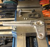
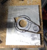
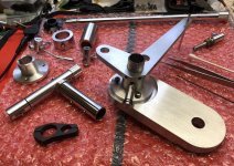
The next part I started working on was the platform to integrate the lift, rest, anti-skate and VTA adjustment. I was able to use the broken plastic Stax piece as a basic template. From there it was a lot of trial and error. Not sure how many times I had to partially assemble and disassemble the arm.
I was sort of winging it with the VTA as I didn’t have the micrometer heads I wanted to try in hand at first.
Some clearances between different components were difficult to resolve like the micrometer mounting and the counter weight.
There was more than one version for the lower contact surface for the micrometer. I thought I had a good solution clamping it to the top of the base. When I got to what I thought was a “final” test fit I realized that there was an interference issue with the bottom of the lift mechanism that required two more machining processes on it to resolve.
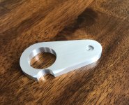
Here are some pics of how I roughed pieces out and worked through it.
I was sort of winging it with the VTA as I didn’t have the micrometer heads I wanted to try in hand at first.
Some clearances between different components were difficult to resolve like the micrometer mounting and the counter weight.
There was more than one version for the lower contact surface for the micrometer. I thought I had a good solution clamping it to the top of the base. When I got to what I thought was a “final” test fit I realized that there was an interference issue with the bottom of the lift mechanism that required two more machining processes on it to resolve.
Here are some pics of how I roughed pieces out and worked through it.
Attachments
-
 36D0A0B8-D7A9-4A92-9EEB-C0349410607E.jpg740.5 KB · Views: 106
 -
 85CB689F-6A5B-40E9-BC06-FC38A65B3C26.jpg531.2 KB · Views: 114
 -
 5670ECB5-C760-460C-8896-38536D7BBF60.jpg1,011.4 KB · Views: 109
 -
 CA6CD290-384A-4EE3-8B02-E19F2B342EC9.jpg1,003.1 KB · Views: 109
 -
 0AEF8BB4-D64F-4E86-A4C5-635FA2F7EF5B.jpg981.7 KB · Views: 101
 -
 305B69EC-8A1E-42CA-ACD9-997F185AA969.jpg1,000.6 KB · Views: 89
 -
 7C5B61A7-0D95-456D-AAC3-30E84D96BB8B.jpg894.3 KB · Views: 80
 -
 790E8C52-45BB-4264-A270-107329E0C345.jpg482.4 KB · Views: 108
 -
 8F550ABE-0795-461D-B98C-93EE01F34C5C.jpg345.5 KB · Views: 118
 -
 F33AE956-E738-450F-B631-08301529B166.jpg821.2 KB · Views: 109
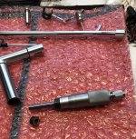
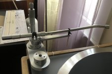
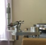
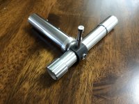
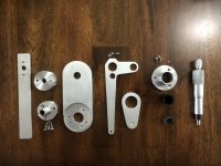
Some more shots of bits and pieces as they got finished and test fitted.
One shot of all the bits I had to fabricate or modify in one way or other.
I actually haven’t set up the anti-skate yet as I was so happy with the sound once I had gone through the basic setup of overhang, VTF and VTA that I decided to just finally enjoy some music again.
I also went back into my “temporary” phono amp again for about the sixth time and added additional inputs, a switch and shielded all the wiring so I could use both the Rega arm and the Stax through it and compare them.
My basic impression is that the Stax/Denon just has more. More detail, more space to the sound stage...more everything. Gain with the additional ZYX pre pre I almost identical to the Rega/Virtuoso combination...perhaps the former having slightly higher output at a given volume setting...or maybe it just sounds like that because there’s MORE.")
One shot of all the bits I had to fabricate or modify in one way or other.
I actually haven’t set up the anti-skate yet as I was so happy with the sound once I had gone through the basic setup of overhang, VTF and VTA that I decided to just finally enjoy some music again.
I also went back into my “temporary” phono amp again for about the sixth time and added additional inputs, a switch and shielded all the wiring so I could use both the Rega arm and the Stax through it and compare them.
My basic impression is that the Stax/Denon just has more. More detail, more space to the sound stage...more everything. Gain with the additional ZYX pre pre I almost identical to the Rega/Virtuoso combination...perhaps the former having slightly higher output at a given volume setting...or maybe it just sounds like that because there’s MORE.
Attachments
-
 86F3AAD7-8653-4561-9164-63205F346D21.jpg854.5 KB · Views: 112
 -
 1D67841D-F0FC-463A-AE01-14135F6FE304.jpg1 MB · Views: 99
 -
 9C1C4A66-9803-4BAD-9160-E7D930F1520D.jpg983 KB · Views: 83
 -
 26BE5055-9872-4B5D-BCEC-E84CAFFA85C0.jpg968.9 KB · Views: 103
 -
 9E332AE4-4EF1-47B1-90CA-BAE39CBCBDEF.jpg975.1 KB · Views: 98
 -
 F0D37F94-8E23-4684-90DD-144F5DBBA249.jpeg654.4 KB · Views: 146
 -
 77B593EF-E1F3-4DC3-BBF2-E855619FC435.jpeg964.9 KB · Views: 179
 -
 2DE1AEB0-2C47-4864-9BAF-F3AFB7DEC05F.jpg713.2 KB · Views: 207
I know this is an old thread but had to say thank you for this. I have 2 HW19's right now (long story). Going to be making a new base. If you have any plans/dimensions/etc of the woodwork it would be appreciated.
I wish I had the tooling you have. I am in a duplex condo now and no space for that kind of tooling. I was a machinist for 14 years. Got the skills, just not the tools!
Thanks again for taking the time to document this.
I wish I had the tooling you have. I am in a duplex condo now and no space for that kind of tooling. I was a machinist for 14 years. Got the skills, just not the tools!
Thanks again for taking the time to document this.
Hi Bpape
Thanks for the kind words. Unfortunately, I don’t have any dimensions for the base.
If I remember correctly, I ripped down some walnut scraps I had to approximately 1” X 1” dimensions and then ripped one edge of the stock a little wider than my blade to create the recess you see between the original oak and the walnut.
I flipped the original oak base over and took measurements to mitre the ends of the pieces. I held them together with a racheting strap with corner guides I bought at Harbor Freight to test fit and finally glue together.
Then I glued/pressed the Walnut frame onto the bottom of the original base and did my sanding/finishing. Pics are in the third post I think.
Last edited:
- Status
- This old topic is closed. If you want to reopen this topic, contact a moderator using the "Report Post" button.
- Home
- Source & Line
- Analogue Source
- VPI resto-mod...a tale of bastardizing my HW19