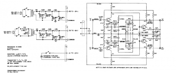
I've been playing with this old shure pre-amp and need advice on adding cartridge loading to the circuit. Have a feeling it's fairly simple but i'm a bit new to this. Any help appreciated greatly.
Shure Publications | Model M61
Edit: Assuming i put a resister and cap to ground before or after the 10uf cap on the input. Manual isnt much help is just states approximately 50k ohm input impedence.
Shure Publications | Model M61
Edit: Assuming i put a resister and cap to ground before or after the 10uf cap on the input. Manual isnt much help is just states approximately 50k ohm input impedence.
Last edited:
The load presented to a cartridge is a combination of the total capacitance of the cables and input of the preamp, along with the resistive load at the preamp, ideally 47K for MM (specified in this case as 50K). Generally, it's pretty close to spot-on already with todays' cartridges. You can increase the capacitive loading by adding a capacitor from the input to ground, and you can adjust the input resistive load by adding a resistor from the input to ground (lowering the input impedance). But I don't know why you would do any of this, unless that pre does a fundamentally better job than a current device (with the proper loading done). It's overall performance is only fair. Why do you want to play with cart loading anyway, got an old cart you want to use with it? The actual way to do that is to use a test record and plot response, then adjust loading for best response. Otherwise it's just a crap shoot.
> performance is only fair.
I think you are being too kind. It was cheap in 1962, and the state of the art has moved a long way since.
It has inherent response errors we would not tolerate today. (Far greater than "cartridge loading" can cause.) It will not handle strong treble. It will not drive a 10K volume pot. The hiss may be marginally tolerable.
This is the kind of thing that gave Germanium a bad name. Not that Ge is bad, but it encouraged good-enough and not-good-enough designs.
I'd never heard of a fad for Ge phono. The strong phono EQ would mask some of what a few Ge fans rave about in mike amps.
Put it in MIC (or whatever), run a guitar through.
Can imagine the response isnt great. That and they added 3db lift from 10khz. I wanted to see if cartridge loading would take the edge off a bit. Adding a 750k parralel resistive load to give me pretty close to 47k on the input. No idea what the capacitive loading is at this point. How do you measure that?
From an engineering point of view your bang on but i have to say the sound out of this thing isnt bad at all. I have a feeling i'm on a fairly steep part of the learning curve with regards to this stuff but having tons of fun playing with this thing.
From an engineering point of view your bang on but i have to say the sound out of this thing isnt bad at all. I have a feeling i'm on a fairly steep part of the learning curve with regards to this stuff but having tons of fun playing with this thing.
Last edited:
Really? Did you simulate the circuit, or have an exact duplicate to measure?It has inherent response errors we would not tolerate today. (Far greater than "cartridge loading" can cause.)
Cart loading on old cart of the same vintage did not have a small effect, quite large in fact. The problem has been largely designed out today.
Again...is this assumption or was there measurement or analysis? I don't disagree with the probable conclusion, but lacking circuit sim or testing, that's why I said "fair" and didn't go stronger.It will not handle strong treble. It will not drive a 10K volume pot. The hiss may be marginally tolerable.
This is the kind of thing that gave Germanium a bad name. Not that Ge is bad, but it encouraged good-enough and not-good-enough designs.
I've never understood the Ge craze. I once designed mic preamp cards to replace stock Ge-based cards in a mixing console and improved total performance in every single aspect, using the same single-pole 24V power supply rails.I'd never heard of a fad for Ge phono. The strong phono EQ would mask some of what a few Ge fans rave about in mike amps.
Put it in MIC (or whatever), run a guitar through.
Last edited:
Really? Did you simulate the circuit, or have an exact duplicate to measure?............
“What’s a CD” - overheard from a school kid. Hurt my soul a little. Made me feel old.
Long before simulation, before a circuit was built, circuits were analyzed *by hand*.
I am sorry if this is too old-fashioned.
Show my work {sigh}.....
Q2's 39K load is not promising for modern 10K-22K inputs. It could be if B+ was very large, but it is not. We also note that the NFB loop load on 39K is 56K mid-band declining toward 5K at the top of the audio band, a very severe load on 39K.
Q1 runs at 0.5mA. re is thus about 60r. This in series with 330r||3k9= 300r, so ~~360r in emitter. Its load is not 56K but hFE*120r, probably ~~5K. Voltage gain of Q1 is around 15. Q2 sees ~~23K midband so runs at gain of 190. OK, 26dB of NFB was "adequate" for 1962.
Since we know the Shure Boys were not fools, we don't need to scratch to see the 50Hz corner is approximate. By the 56K midband RIAA resistor we expect ~~500K-600K for 50Hz corner. We find over 1.5Meg, 3X more than an "ideal" amp, so they were really short of bass gain.
The 0.5mA in Q1 promises high current-hiss against the rising cartridge impedance. True, with needle in the groove this may not be the playback noise level.
And while it is a matter of taste, IMHO it is extremely difficult to get "good RIAA" with just two transistors, even modern high-hFE parts. Three is so much better. Your opinion may vary.
It's a rather interesting design, and better than I would have expected in that time frame.
There are two feedback loops, one for DC only for stabilization of the operating point. The input is boot-strapped to get the input impedance up.
It doesn't seem to have a huge amount of headroom as PRR points out.. Output impedance is rather high.
I'd go through and do a recap of the electrolytics in this thing fairly soon.
I would have little difficulty in accepting that it sounds a lot better than one would expect given the vintage.
They really cheaped out on the 210 - 240V supply.. LOL
Attachments
I would probably replace that power supply with something a little more modern..
The 10K and 22K resistors should be replaced and I would probably go with 5W and 2W resistors respectively. Metal oxide or wirewounds would be appropriate. I think you ought to add a fuse - 100mA time delay ought to be sufficient.
The 10K and 22K resistors should be replaced and I would probably go with 5W and 2W resistors respectively. Metal oxide or wirewounds would be appropriate. I think you ought to add a fuse - 100mA time delay ought to be sufficient.
This Phono preamp, I gathered 2 years ago . Telefunken produced this scheme under the brand name of the TV 206 . I have produced a stabilized power supply . And added a single transistor on the output . This preamp sounds very interesting . Germanium sound I really like .Germanium phono preamp ( sch.) - Vinyl Engine ...Power supply for germanium phono - Vinyl Engine ....Germanium phono preamp (5) - Vinyl Engine ...Germanium phono preamp (3) - Vinyl Engine ...Germanium phono preamp (7) - Vinyl Engine ...https://www.vinylengine.com/turntable_forum/gallery/image_page.php?album_id=105&image_id=35007 ...
Last edited:
Measurements of germanium preamp . Frequency response and harmonics . The program RMAA . The output signal preamp 2 volts / 1 kHz ( peak-to-peak ) . Gain 42 db . Harmonics - 0,017 % ...Simple good preamp ...Long live Shure and Telefunken ! ))))....Germanium Phono ( spectrum ) - Vinyl Engine ...Germanium phono ( THD ) - Vinyl Engine ...
Last edited:
Phono preamp Telefunken TV-206 .... Phono preamp Telefunken TV 206 - Vinyl Engine ...
I had more than a dozen different phonopreamp . The sound of the germanium preamp I really like . Before that, several years used the preamp in the Yamaha scheme A1 ..... Germanium sounds interesting .It Shureis a fun little preamp with a nice sound. And thank you for the links, I'll be checking those out for Shure

- Status
- This old topic is closed. If you want to reopen this topic, contact a moderator using the "Report Post" button.
- Home
- Source & Line
- Analogue Source
- Shure M61 RIAA Cartridge Loading