Hi thanks for the reply, can I ask how you identified the op amp just in case I need to replace with identical component?
I am confused about the configuration of the op amps - I have to admit. I assumed there was one for each channel. Are you saying that each op amp is inputting and outputting signal to each speaker?
My scope ground is connected to the back side chassis rubber and I probe each pin with the signal generator inputting to each channel per test, with the output RCA going to a resistive load. The scope dc coupled.
The outputs measured in the scope are:
..........OA R........OA L
Pin 1 : 4.7V ____ 2.2V 1kHz sine wave
Pin 7: 2.4V ____ 2.2V 1kHz sine wave
Last edited:
Even though ARTs website states
Simply send an email to support@artproaudio.com. Be sure to include the model name! We'll send you an Adobe .pdf file with the schematic you requested. PLEASE NOTE: Schematics are not released for new products still under warranty. (e.g. Tubefire8)
My unit is out of warranty but they will not provide one.
Key things to know at the outset...
What devices are U2,3 and U4
Which device of those is the signal applied to for the right channel.
Assuming U2,3 and 4 are dual opamps, do they share left and right duties per opamp throughout the preamp or are any used exclusively for one channel.
Again, assuming duals, one must be shared if the other two are not.
I have tried to follow your thread, but so far it has been very confusing.
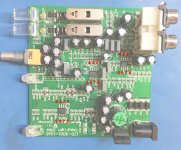
1) That's why I have copied your Image below, now with inserted pin numbers.
That makes that no misunderstanding can exist where you are measuring.
2) From the data you provide it is unclear whether you mean AC or DC.
3) Using a 1KHz signal at the input is O.K. but 80mV is far above the 40mV max that ART specifies, so try to take this back to 14mV
4)Put the gain switch in the 0dB position, gain will now be 37dB, giving 1V output signal from the 14mV input, still below the 1.4V max out that ART specifies.
Now make a list for U2 to U4, specifying for all 8 pin numbers what you measure with the 14mV applied at the input.
Something like
U2: Pin 1: 14mV 1Khz, Pin 2: 5 Volt DC, Pin3: 0V DC, Pin 4: 500mV 1Khz, Pin 5: 100mV AC noise, etc.
U3: .......
U4: ........
With that table at hand will it be possible to help you in a much better way.
Hans
Attachments
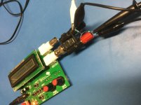
Function generators usually want to see at least 600 Ohm or more.Just a quick question. How to I attenuate the signal coming out of the function generator? I need to drop it by more than half.
So If you need to drop by ca. 25%, use 150 Ohm + 470 Ohm. and take the 150 Ohm as your signal output.
I tried this and a 100/1k voltage divider but don’t see any effect. The signal is very unstable at the lowest output with this cheap eBay signal source and even with the attenuator components, I cannot get anything stable below 100mVpp.
Not sure if I am doing this right. Not even sure if I have suitable equipment.
Not sure if I am doing this right. Not even sure if I have suitable equipment.
Attachments
Last edited:
I think you have the resistors the wrong way around - hence the signal applied to the amplifier is about 0.91 of the signal generator output. The 100ohm resistor should be between the input terminals and the 1kohm resistor between the function generator output and the amplifier input.
Thanks, that is better. Quite jittery but can now hold 40mVpp easily. Should be able to start doing the suggested testing and answering questions tomorrow.
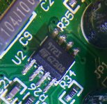
Are you able to identify this component? It is one of the three packages on the PCB. i cannot find anything on the web.
Thanks
Are you able to identify this component? It is one of the three packages on the PCB. i cannot find anything on the web.
Thanks
Attachments
Last edited:
It's probably a TL972.
http://www.ti.com/lit/ds/symlink/tl972.pdf
From ST the component is called TS972
http://www.st.com/content/ccc/resou...df/jcr:content/translations/en.CD00001508.pdf
Hans
http://www.ti.com/lit/ds/symlink/tl972.pdf
From ST the component is called TS972
http://www.st.com/content/ccc/resou...df/jcr:content/translations/en.CD00001508.pdf
Hans
Last edited:
It could be a STMicroelectronics TS972, low noise dual opamp, as it is marked 972I and has the STM logo. The datasheet is readily available:
TS972 - Output rail-to-rail very low-noise op-amps - STMicroelectronics
TS972 - Output rail-to-rail very low-noise op-amps - STMicroelectronics
A quick DC voltage check would be very worthwhile as an initial step.
Do a copy and paste of this and add the readings.
U2
Pin 1 =
Pin 2 =
Pin 3 =
Pin 4 =
Pin 5 =
Pin 6 =
Pin 7 =
Pin 8 =
U3
Pin 1 =
Pin 2 =
Pin 3 =
Pin 4 =
Pin 5 =
Pin 6 =
Pin 7 =
Pin 8 =
U4
Pin 1 =
Pin 2 =
Pin 3 =
Pin 4 =
Pin 5 =
Pin 6 =
Pin 7 =
Pin 8 =
Do a copy and paste of this and add the readings.
U2
Pin 1 =
Pin 2 =
Pin 3 =
Pin 4 =
Pin 5 =
Pin 6 =
Pin 7 =
Pin 8 =
U3
Pin 1 =
Pin 2 =
Pin 3 =
Pin 4 =
Pin 5 =
Pin 6 =
Pin 7 =
Pin 8 =
U4
Pin 1 =
Pin 2 =
Pin 3 =
Pin 4 =
Pin 5 =
Pin 6 =
Pin 7 =
Pin 8 =
With the 40mV sine wave input signal into the amp, for the working and faulty channel?
A quick DC voltage check would be very worthwhile as an initial step.
Do a copy and paste of this and add the readings.
U2
Pin 1 =
Pin 2 =
Pin 3 =
Pin 4 =
Pin 5 =
Pin 6 =
Pin 7 =
Pin 8 =
U3
Pin 1 =
Pin 2 =
Pin 3 =
Pin 4 =
Pin 5 =
Pin 6 =
Pin 7 =
Pin 8 =
U4
Pin 1 =
Pin 2 =
Pin 3 =
Pin 4 =
Pin 5 =
Pin 6 =
Pin 7 =
Pin 8 =
I was thinking just DC voltages to begin with, but if you want to add the AC voltage as well then that would be great. You need to be sure the same signal is applied to both inputs and the easiest way to ensure this might be just to tag a link between the phono sockets centre pins.
Its the wrong end of the day here") but I'll look in tomorrow all being well.
but I'll look in tomorrow all being well.
Its the wrong end of the day here
but I'll look in tomorrow all being well.- Status
- This old topic is closed. If you want to reopen this topic, contact a moderator using the "Report Post" button.
- Home
- Source & Line
- Analogue Source
- Phono Pre-amp fault