I have come into possession of a decent condition Sansui SR525. The brushless DC motor doesn’t turn but I thought I’d check it out and if I don’t have any luck I would use the arm as a second arm on my Lenco.
When I first power on there is a slight movement of the motor. If I try again it doesn’t move at all until I leave it for a while. The strobe light lights up.
I checked the power to the motor and measure +15.9 and -5. It should be +18 and -5 according to the manual.
I opened up the motor hood which appears to have not been opened before. The board looks fine and measures 15.9V/-5 at the input. I think it measured the same on both speed settings which I didn’t expect.
Has anyone any experience with this TT?
Thanks,
kffern
Is it worth looking into. There are a couple of good techs locally but not sure if its worth paying for the repair. Some reviews claim its better than the SL1200 and I do think it looks good.
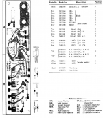
Attachments
You might get lucky.
You should definitely be seeing 18 volts rather than 16 or so.
First check would be to see if the regulator TR101 is getting hot which would suggest an overcurrent situation ?
Thanks I will do that. TR101 didnt show any signs of overheating but I guess it would be the first thing to change. There are a few on ebay but nothing local.
Do you know of an alternative? The complementary p-n-p transistor to 2SD313 is 2SB507. I would prefer the same pinout if possible.
Characteristics of the bipolar transistor 2SD313
Type - n-p-n
Collector-Emitter Voltage: 60 V
Collector-Base Voltage: 60 V
Emitter-Base Voltage: 5 V
Collector Current: 3 A
Collector Dissipation - 30 W
DC Current Gain (hfe) - 40 to 320
Transition Frequency - 5 MHz
Operating and Storage Junction Temperature Range -55 to +150 °C
Package - TO-220
Regards,
kffern
Don't just change it in hope... see if its getting hot. If it is then its probably OK and excess current draw is pulling the voltage down.
Next step would be to check the voltage on the collector and on the base. There should be around 25 volts as a guestimate on the collector (actual values depends on transformer voltage) and a very definite 19 volts on the base.
Other possibilities for this fault could include dried out and failed electrolytic caps.
Don't just change it in hope... see if its getting hot. If it is then its probably OK and excess current draw is pulling the voltage down.
Next step would be to check the voltage on the collector and on the base. There should be around 25 volts as a guestimate on the collector (actual values depends on transformer voltage) and a very definite 19 volts on the base.
Other possibilities for this fault could include dried out and failed electrolytic caps.
The transistor is heating up. stops around 40degC. I'm not sure if I'm doing this correct but I only get around 4to 4.6V between collector and emitter and base.
The caps look brand new. No bulging, heating or leaking.
I could change the caps and see what happens.
Thanks,
kffern
Do you have a laboratory power supply to check if the DC motor works?
No. I don't but after changing the caps I may access one.
kffern
Replacing the caps would be a smart move I suspect and the cost is minimal. Provided there is no physical damage to the parts that can't be replaced such as the stators and so on then rebuilding the board would still cost very little.
Its hard to fault find on this logically without a scope but there are several static tests that can be done such as checking B-E voltages on the drive transistors and making sure none are doing anything silly. You should see no more than around 0.7 volts across each junction.
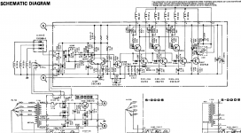
I suspect the regulator is probably OK and it is the simply voltage being pulled down giving the low reading although if I'm honest I'm struggling to see how the circuit actually works. There doesn't seem to be a supply voltage applied to the stators and I'm wondering if there is a 'blob' missing on the diagram in the region of 'pin 9' on the stator connections.
Its hard to fault find on this logically without a scope but there are several static tests that can be done such as checking B-E voltages on the drive transistors and making sure none are doing anything silly. You should see no more than around 0.7 volts across each junction.
I suspect the regulator is probably OK and it is the simply voltage being pulled down giving the low reading although if I'm honest I'm struggling to see how the circuit actually works. There doesn't seem to be a supply voltage applied to the stators and I'm wondering if there is a 'blob' missing on the diagram in the region of 'pin 9' on the stator connections.
Well, I have finally changed all the caps and still nothing. The boards are really well made and desoldering and resoldering was quite easy. I didn't take a picture of the finished job though. I did the power supply and checked it before going onto the control board. Less than $5 worth of capacitors. Only one of the power caps made me feel like it needed to be changed. It hissed and buzzed when I touched the soldering iron and leaked a bit as well.
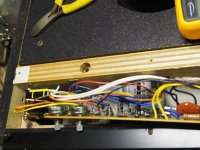
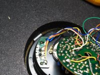
I don't read anything at the 3 inputs to the motor, AC or DC. I don't think I checked properly before i changed the caps though. Picture 3 - between blue, brown, yellow and white. I wish I new what voltage to expect.
The three inputs to the motor make me feel like building pyramids controller which I haven't got down to as yet.
I guess should try the power supply transistor next. I can get a MJE15032G locally.
Regards,
kffern
Attachments
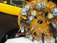
The transistor is marked Sanyo D313 ? 9J. The ? mark stand for what looks like an upside down L. It doesn't look like an E with the middle and bottom crosses wiped out as there isn't any trace of them. Google doesn't come up with anything.
If its an E or an F it has a current gain of 100 to 320 is all I can find.
What I do notice is that when power is switched on the spindle moves minutely backwards and then it is harder to turn the spindle either way. With power off it turns freely. I did pull of the rotor to check the bearing and it looks good. Small dimple in the teflon thrust pad but I didn't turn it over just yet.
kffern
Last edited:
Which of the caps on the diagram was the one the hissed and buzzed ? Any chance it leaked previously onto the board ?
The reason the rotor is hard to turn when power is on is because one or more of the coils is permanently energised and so acting as a magnetic brake.
Before you change any transistors lets try a bit of measurement and sneaky testing to see if we can get a feel for what is happening.
Do you see each pair of drive transistors, Q001 and Q004, Q002 and Q005, Q003 and Q006
See if you have the same DC voltage on each like for like transistor, or does any pair stand out as different.
There are 3 parallel 6.8 ohm resistors making an effective value of 2.2 ohms. What DC voltage is across those resistors ?
What DC voltage is on Q008 base and emitter ?
What DC voltage is on Q007 collector ?
Which of the caps on the diagram was the one the hissed and buzzed ? Any chance it leaked previously onto the board ?
It was C103. It hadn't leaked before I removed it. The board was clean.
I will try and check as you suggest later today when back from work.
Thanks for your help.
Regards,
Kffern
Ah, the little negative rail generator. Interesting ") That's a classic failure mode for a cap used in that way. The cap is small and the ripple current surprisingly high. These days you might find something like a 10 ohm series resistor added to the diode to limit the very small time duration, but very high magnitude current pulses.
That's a classic failure mode for a cap used in that way. The cap is small and the ripple current surprisingly high. These days you might find something like a 10 ohm series resistor added to the diode to limit the very small time duration, but very high magnitude current pulses.
I see I mentioned checking Q008 B and E. That should have read B and C (as E is grounded).
There is also a 16 volt zener generating a stable supply for the oscillator located at the left of the circuit. Check that there is approx. 16 volts across that device.
That's a classic failure mode for a cap used in that way. The cap is small and the ripple current surprisingly high. These days you might find something like a 10 ohm series resistor added to the diode to limit the very small time duration, but very high magnitude current pulses.I see I mentioned checking Q008 B and E. That should have read B and C (as E is grounded).
There is also a 16 volt zener generating a stable supply for the oscillator located at the left of the circuit. Check that there is approx. 16 volts across that device.
Q004 - 0, Q005 - 14.4v, Q006 - 14.4VDo you see each pair of drive transistors, Q001 and Q004, Q002 and Q005, Q003 and Q006. See if you have the same DC voltage on each like for like transistor, or does any pair stand out as different.
Q001 - 0, Q002 - 11.6, Q003 - 11.5
6.6VThere are 3 parallel 6.8 ohm resistors making an effective value of 2.2 ohms. What DC voltage is across those resistors ?
4.58VWhat DC voltage is on Q008 base and emitter ?
14.6VWhat DC voltage is on Q007 collector ?
4.97V. with the probes at either end of the zener. Hope thats what you meant.There is also a 16 volt zener generating a stable supply for the oscillator located at the left of the circuit. Check that there is approx. 16 volts across that device.
Hope I have your instructions correct. I also measured across 1 and 2 - 12.2V, 3 & 4 - 2.2V and 5 & 6 - 2.2V. I assumed that is what is getting to the coils?
Thanks very much for your help Mooly.
Regards,
Kffern
A lot to look at here
The pairs of drive transistors. There seems to be something going on around that first pair but we need to know where you are measuring. There are really 18 separate measurements for those 3 pairs, C,B and E of each and for all 6 transistors.
I would have expected all 3 pairs to be the same whatever the actual reading comes in at.
That is worth looking at in more detail. Its only a few minutes work
Now, something really doesn't add up here... those parallel 6.8 ohms with over 6 volts across them. That equates to a current of 3 amps !!!
There is a possibilty here that if there is some AC component present e.g. the circuit is actually trying to run, that the AC component could give a misleading result on the meter.
Can you recheck that result and also with the unit OFF check that they do indeed read approx. 2.2 ohms as measured in circuit. Lets be sure they haven't gone high in value.
Lets see what all that throws up first.
The 16 volt zener reading is very low and again there are a few possibilities for that.
Do you see another parallel set of resistors feeding the zener ? Its worth checking those are OK.
A quick and dirty check of the zener (to prove its not leaky) is to lift one end of it and see if the voltage comes up on the board.
And lets be sure on those drive transistors. C,B and E for each like device I would expect at this stage to be similar.
A lot to look at here
The pairs of drive transistors. There seems to be something going on around that first pair but we need to know where you are measuring. There are really 18 separate measurements for those 3 pairs, C,B and E of each and for all 6 transistors.
I would have expected all 3 pairs to be the same whatever the actual reading comes in at.
Q004 - 0, Q005 - 14.4v, Q006 - 14.4V
Q001 - 0, Q002 - 11.6, Q003 - 11.5
Sorry forgot to include that these are from B to C for both with power on. I did check the sheets but its hard to turn the board upside down and get the right pads. It is very cramped and still wired up.
I will try and double check these tonight.
I did check these and combined it was coming to around 3.2 if I remember correct. I remember it was a bit higher than 2.3 which I calculated. I will check again tonight.Can you recheck that result and also with the unit OFF check that they do indeed read approx. 2.2 ohms as measured in circuit. Lets be sure they haven't gone high in value.
Regards,
kffern
Last edited:
Low value resistors can be tricky to measure. First see what your meter reads with the probes shorted together as that reading will have to be subtracted from the measured value. Typically you see around 0.1 or 0.2 ohm.
Also visually check the colour code of the resistors. The manufacturer may have fitted something else to what is shown on the circuit.
These transistors
What I was trying to determine was whether the output transistors of the pair were being turned on or not and whether all behaved the same. That measurment is the collector voltage of Q004/5 and 6.
Applying a temporary short across Q008 collector and emitter should turn them all off and I would expect the voltage across the 6.8 ohms to fall and for the turntable to be 'free' to rotate manually.
Oops. That should have been 0.66VNow, something really doesn't add up here... those parallel 6.8 ohms with over 6 volts across them. That equates to a current of 3 amps !!!
According to google that zener is actually a 5.1v. xz051. The 16v is the 47uF cap rating. Its the only zener on the motor board.The 16 volt zener reading is very low and again there are a few possibilities for that.
Measuring the resistors accurately may be difficult with my DMM. I will buy some low R resistors tomorrow and compare.
Regards,
kffern
- Status
- This old topic is closed. If you want to reopen this topic, contact a moderator using the "Report Post" button.
- Home
- Source & Line
- Analogue Source
- Sansui SR525 doesn't turn