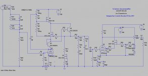
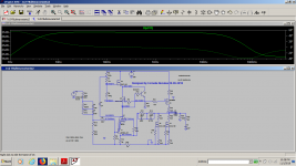
This is my last project, ready to be assembled:

http://i68.tinypic.com/or709w.jpg
User Media - TinyPic - Free Image Hosting, Photo Sharing & Video Hosting
I am not an experienced user of LtSpice, nor a good designer so please bear with me!
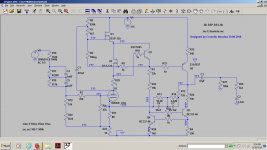
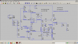
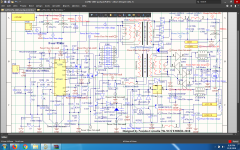
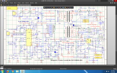
The version i built is with d3a as pentode in constant vg2k mode as in Tektronix vertical amplifier manual.
The model for d3a in triode mode is the Bartola model.
The bss-135 transistors are just models as the real transistors were bsp-135.
I didn't know how to convert the orcad spice models for bsp125 and bsp135 to LT-spice but a romanian mate, G Sabac, helped me with bsp125 conversion to lt-spice and suggested that bss-135 would approximate the bsp-135.He is the one who gave me the bsp-bss library attached in zip format.
I have to thank jazbo8 for helping me with the the model for d3a as a pentode.
V2 can be 160...190v, but with lower voltages a transistor like pzta42 or a swithing transistor like zetex would work better.Even bc337/40 is better than ksc3503 with lower voltages .Unfortunately it's a bit dangerous in tranzient mode to have a bc337,myght work though....
The riaa network i chose is about 10k impedance, but the sym shows that a 600 ohm lcr network can be ok too with increased thd , but very monotonic decay of h2, h3, h4...
You can see that i used a 470 ohm (wirewound LESA) potentiometer in the riaa network(R23-R25) that allows me to modify the response as a mid-high corrector.
I chose c3 100uf to work as a steep ruble filter with R13-R16 which are in fact a 100 ohm wirewound pot, so i can raise the gain too with that.Of course i can change c3 for a higher value and have a better base response.
The two zenners are in fact just one of 150v...
V3 is just a 1.5v battery.It can be replaced with a 1.2v for higher current and lower noise in the input stage.
I still am curious about the partition noise of the second stage , now that i have a fet providing the constant voltage.
Of couse you can modify the values for your preffered response...
The inverse riaa is a slight modification of this:
https://i0.wp.com/www.bartola.co.uk/valves/wp-content/uploads/2013/12/Hagermans-IRIAA-circuit.png

http://i66.tinypic.com/18esxt.jpg
User Media - TinyPic - Free Image Hosting, Photo Sharing & Video Hosting

http://i64.tinypic.com/315ohmg.jpg
http://tinypic.com/m/k0iwlx/1
This is part of a slightly bigger project that includes also my Teardrop headphones amplifier , a hybrid project too.I'm going to make a different thread for that too, but the main transformers are in the headphone amplifier box so they would work together.
You have just some pictures of the Teardrop headphones amplifier for which G Sabac put together the BSP-BSS models and made a simulation here:
https://www.elforum.info/topic/128710-teardrop-headphones-amplifier/
Unfortunately you need to register there and translate from romanian if you want to see that thread.
My real amp sticks a bit to the first version though as i found a better monotonic decay in fft response with higher current in the first stage, but took his advice for higher voltage in the first stage.

http://i68.tinypic.com/ea39ly.jpg
http://tinypic.com/m/k0iyrb/1

http://i68.tinypic.com/2i1iohu.jpg
http://tinypic.com/m/k0iyrp/1
This will be discused also in a separate thread .
http://i68.tinypic.com/or709w.jpg
User Media - TinyPic - Free Image Hosting, Photo Sharing & Video Hosting
I am not an experienced user of LtSpice, nor a good designer so please bear with me!
The version i built is with d3a as pentode in constant vg2k mode as in Tektronix vertical amplifier manual.
The model for d3a in triode mode is the Bartola model.
The bss-135 transistors are just models as the real transistors were bsp-135.
I didn't know how to convert the orcad spice models for bsp125 and bsp135 to LT-spice but a romanian mate, G Sabac, helped me with bsp125 conversion to lt-spice and suggested that bss-135 would approximate the bsp-135.He is the one who gave me the bsp-bss library attached in zip format.
I have to thank jazbo8 for helping me with the the model for d3a as a pentode.
V2 can be 160...190v, but with lower voltages a transistor like pzta42 or a swithing transistor like zetex would work better.Even bc337/40 is better than ksc3503 with lower voltages .Unfortunately it's a bit dangerous in tranzient mode to have a bc337,myght work though....
The riaa network i chose is about 10k impedance, but the sym shows that a 600 ohm lcr network can be ok too with increased thd , but very monotonic decay of h2, h3, h4...
You can see that i used a 470 ohm (wirewound LESA) potentiometer in the riaa network(R23-R25) that allows me to modify the response as a mid-high corrector.
I chose c3 100uf to work as a steep ruble filter with R13-R16 which are in fact a 100 ohm wirewound pot, so i can raise the gain too with that.Of course i can change c3 for a higher value and have a better base response.
The two zenners are in fact just one of 150v...
V3 is just a 1.5v battery.It can be replaced with a 1.2v for higher current and lower noise in the input stage.
I still am curious about the partition noise of the second stage , now that i have a fet providing the constant voltage.
Of couse you can modify the values for your preffered response...
The inverse riaa is a slight modification of this:
https://i0.wp.com/www.bartola.co.uk/valves/wp-content/uploads/2013/12/Hagermans-IRIAA-circuit.png
http://i66.tinypic.com/18esxt.jpg
User Media - TinyPic - Free Image Hosting, Photo Sharing & Video Hosting
http://i64.tinypic.com/315ohmg.jpg
http://tinypic.com/m/k0iwlx/1
This is part of a slightly bigger project that includes also my Teardrop headphones amplifier , a hybrid project too.I'm going to make a different thread for that too, but the main transformers are in the headphone amplifier box so they would work together.
You have just some pictures of the Teardrop headphones amplifier for which G Sabac put together the BSP-BSS models and made a simulation here:
https://www.elforum.info/topic/128710-teardrop-headphones-amplifier/
Unfortunately you need to register there and translate from romanian if you want to see that thread.
My real amp sticks a bit to the first version though as i found a better monotonic decay in fft response with higher current in the first stage, but took his advice for higher voltage in the first stage.
http://i68.tinypic.com/ea39ly.jpg
http://tinypic.com/m/k0iyrb/1
http://i68.tinypic.com/2i1iohu.jpg
http://tinypic.com/m/k0iyrp/1
This will be discused also in a separate thread .
Attachments
As usual i put the wrong simulation and jpeg...It happened because before uploading i tried to make the image smaller so i scrambled both simulation and image.R18 was linked to the wrong point.Actually it worked like that in the sym and the fft seemed to be the same, but h2 was by 3db higher.Not that i fully trust my syms...i don't really know if they are very correct.I barely knew how to load the sym models...
Attachments
Last edited:
Instead of a battery, why not an LED in the cathode of the first stage?
Take a look at the front end of SY's design "His Master's Noise" : His Master's Noise: A Thoroughly Modern Tube Phono Preamp
Take a look at the front end of SY's design "His Master's Noise" : His Master's Noise: A Thoroughly Modern Tube Phono Preamp
This is my second design based on d3a, the first is here:
UNU-pnono riaa mm preamp
I used a battery to bias the second stage there, but i never showed the second stage on diyaudio.It was quite complex and not very effective on low impedances as it was allan kimmel mu stage but built fully with tubes .
Among all the phono stages based on d3a, the one i allways envied is the ""Izzie wizzie ""design and i used his battery arangement for the first stage just to see how it will work like that.
1.9v on the red led...i think a green one would be 1.8...1.9 v
Anyway my design works with really cheap transistors and it can go really low with the voltage as it works very close to the saturation of the transistors.I tried to make Allan Kimmel's design pure transconductance mu stage removing any resistor as load .I didn't want to go the ccs way for anode.Voltage source is better for this design as the efficiency can be much higher than the one of any ccs .I will try to go with 100...130v as supply for the first stage to see how it works.
Anyway my design works with really cheap transistors and it can go really low with the voltage as it works very close to the saturation of the transistors.I tried to make Allan Kimmel's design pure transconductance mu stage removing any resistor as load .I didn't want to go the ccs way for anode.Voltage source is better for this design as the efficiency can be much higher than the one of any ccs .I will try to go with 100...130v as supply for the first stage to see how it works.
Thanks Bogdan!
I built yesterday the capacitor and resistor network swich for loading the cartridge for both mm and mc carts.
I simulated today with the japanese spice model for d3a and their thd results measure worse by 4...6 db which i trust more") .
.
I also spent some hours to simulate a fet input placed in the d3a cathode for an mc cart input and i found a simple way to swich from valve input to fet input so that i will use the d3a grid for mm cart and fet input for mc.I tried with lsk489, but i would use bf862.I can't download today the bf862 model so i will look tomorrow for that.
I built yesterday the capacitor and resistor network swich for loading the cartridge for both mm and mc carts.
I simulated today with the japanese spice model for d3a and their thd results measure worse by 4...6 db which i trust more
.I also spent some hours to simulate a fet input placed in the d3a cathode for an mc cart input and i found a simple way to swich from valve input to fet input so that i will use the d3a grid for mm cart and fet input for mc.I tried with lsk489, but i would use bf862.I can't download today the bf862 model so i will look tomorrow for that.
I also found that i have no output atenuation down to 120v dc for the first valve supply.I csn still go down to 100v with about 25% output atenuation with current values.I also used bc337/40 more in the model as it shows better figures but i'll probably go with ksc1845 if they blow up.They are protected by the surrounding circuit and they won't blow, i think...
I finally got the time to put everything together: my headphones amplifier in one box that contain the regulators and the power supply and the phono preamplifier in another box.The real thing has now a e282f pentode in the second stage of the phono preamp as d3a wasn't necessary there, the gain was huge and the second stage was delivering way too high output for any amplifier at full gain .After replacing it with e282f and raising the cathode resistor to 200 ohms adding 100 ohms to the actual 100 ohms potentiometer , the gain was still very high but cleaner as the bias raised to -2.5...-3v .I tried many different aproaches for bias in the first stage and gave a try to an infrared led as in ''His master's noise'' approach.What i could see against other methods was that the gain now is the highest possible.The sound is good, honestly.I cannot believe anymore there's anything bad about using led's for biasing valves, but now i rely only on the mu-follower stage for reducing distortions and i had the impression that a resistor in the cathode is taming this stage a bit better especially because i'm dealing with a huge transconductance for a valve, not to mention that without a current source in the anode there's virtually no way to have equal currents and gain in both channels.I felt at some point that using a battery to raise the positive bias and a higher value cathode resitor to substract back the bias to the negative value gave me the best results but ir led is fine and very cheap for what it does.Actually there's clear indication that there's nothing wrong with using ir led's in the signal path.There's no alteration to the sound.
Another small problem that i have is that i have a bit of hum on 100hz over the signal .The s/n ratio is very high anyway as the total gain but the hum is somehow annoying and i'm still looking to reduce it further.
I raised the fillament potential to +30v but it's not that.I think i just have very poor psrr in the second stage as the first stage suffered enough alterations with no result whatsoever.Still it's a mistery to me this hum as everything is star ground , no shileding helps, no resistor-capacitor decoupling helps.I'm still digging.The hum is deffinetly in the phono section aria as the headphones amplifier is super clean.What's not figgured in the schematic is the resistor and capacitor network switch in the input for matching every possible cartridge.I even have a section for mc cartridge loading but there's no mc input pre-pre yet.I also have 4 slow start regulators for every filamment in the phono section, a second regulator for the 165 anode voltage too.
http://i63.tinypic.com/988wu8.jpg
User Media - TinyPic - Free Image Hosting, Photo Sharing & Video Hosting
http://i67.tinypic.com/kbucsh.jpg
User Media - TinyPic - Free Image Hosting, Photo Sharing & Video Hosting
http://i64.tinypic.com/212srkg.jpg
http://tinypic.com/m/k1846t/1
http://i64.tinypic.com/2mz9sly.jpg
http://tinypic.com/m/k18478/1
http://i63.tinypic.com/zipy0y.jpg
Another small problem that i have is that i have a bit of hum on 100hz over the signal .The s/n ratio is very high anyway as the total gain but the hum is somehow annoying and i'm still looking to reduce it further.
I raised the fillament potential to +30v but it's not that.I think i just have very poor psrr in the second stage as the first stage suffered enough alterations with no result whatsoever.Still it's a mistery to me this hum as everything is star ground , no shileding helps, no resistor-capacitor decoupling helps.I'm still digging.The hum is deffinetly in the phono section aria as the headphones amplifier is super clean.What's not figgured in the schematic is the resistor and capacitor network switch in the input for matching every possible cartridge.I even have a section for mc cartridge loading but there's no mc input pre-pre yet.I also have 4 slow start regulators for every filamment in the phono section, a second regulator for the 165 anode voltage too.
An externally hosted image should be here but it was not working when we last tested it.
http://i63.tinypic.com/988wu8.jpg
User Media - TinyPic - Free Image Hosting, Photo Sharing & Video Hosting
An externally hosted image should be here but it was not working when we last tested it.
http://i67.tinypic.com/kbucsh.jpg
User Media - TinyPic - Free Image Hosting, Photo Sharing & Video Hosting
An externally hosted image should be here but it was not working when we last tested it.
http://i64.tinypic.com/212srkg.jpg
An externally hosted image should be here but it was not working when we last tested it.
http://tinypic.com/m/k1846t/1
http://i64.tinypic.com/2mz9sly.jpg
An externally hosted image should be here but it was not working when we last tested it.
http://tinypic.com/m/k18478/1
http://i63.tinypic.com/zipy0y.jpg
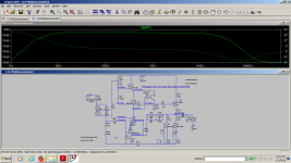
The voltage values in the simulations are not true as i suspected that there's something wrong about the bss135 model.The first stage has a totally different behaviour below 19.5ma and over 20ma in the simulation , which is not real.The d-s voltage of bss135 in the anode of d3a is in fact higher than predicted by the model which is actually better and i was expecting that anyway.
Allthough i still aim for lower hum , the sound is really good and powerfull as i expected.I have many solid state phono preamps but valves sound better no matter how you take it.I used transistors here to help the valve deliver more current into the riaa network and it does the job very well.I played for about two months with simulations and i could derive a few working models that can serve me very well as some of them can withstand 100x higher input or 500mv on the input with no clipping in the first stage and very predictible clipping in the second stage function of what valve and bias you use.I just wanted to have the higher possible output signal and the best s/n ratio that i can get with a passive network within reasonable limits for the complexity of the schematic whih is still 2 stages amplifier with no global feedback.
Allthough i still aim for lower hum , the sound is really good and powerfull as i expected.I have many solid state phono preamps but valves sound better no matter how you take it.I used transistors here to help the valve deliver more current into the riaa network and it does the job very well.I played for about two months with simulations and i could derive a few working models that can serve me very well as some of them can withstand 100x higher input or 500mv on the input with no clipping in the first stage and very predictible clipping in the second stage function of what valve and bias you use.I just wanted to have the higher possible output signal and the best s/n ratio that i can get with a passive network within reasonable limits for the complexity of the schematic whih is still 2 stages amplifier with no global feedback.
I finally got rid of the hum.I just inserted one resistor in between two capacitors on the main 285 v supplying the second stage as i had no regulator there and the psrr was poor.Then i wired the e282f in triode mode as the gain was too high.It still is insanely high.In order to further reduce the gain to acceptable levels i removed the IR led and moved the 68 ohm resitor used to decouple the input ground in the LED's place.The 68 ohm decoupling was irrelevant to the hum level as now is really low.The 68 ohm resistor looks like providing a bit of negative feedback which i find benign.It's true that this resistor raised the white noise level a bit, compared to the IR led but it's really low anyway .I'm not going to dismiss the use of an LED as it looks like the lowest noise method for biasing a valve , but i preffered the cathode resistor with no capacitor in paralel .The sound is incredibly good anyway .Output level is insanely high.I mean...i can't understand those who tell that the digital world offers a far better s/n ratio.It's irrelevant as the noise level is as low as you'd ever need with an mm cart connected to a valve phono preamplifier with passive riaa network .All i need more for this preamplifier is an input transformer for mc cart and a better output potentiometer with pairs of resistors to have each level done by just two resistors . I allready have the loading section for mc cart on the front of the pannel. I don't even have the best mm cart, i have an obscure Onkyo cart which sounds better to my ears that Shure mm75d .I have three shure m75d and they don't offer what this Onkyo does.It tracks allmost anything.The only song i felt it couldn't track well was The Motherboard by Daft Punk, but i suspect that the vinyl realease is not good enough unless i need a different stylus for that alone.Kraftwerk, Tori amos, Tubullar bells, Jeff wayne's world's war, SADE-best of, Tiffany 45 rpm disco dub, Handel organs, Jim Horn -Neon nights, all of them made my day today.I'm finally happy and looking for a new task.
Last edited:
Actually i was wrong again...allthough there's indeed a significant higher ds voltage than the simulation predicted, higher enough to provide linear response , i found that around 20ma there's actually a very sharp increase of vds with the current through it..I don't know yet if it's related to gm of the real bsp135 or the valve's gm itself because the anode voltage go naturally lower with the valve's bias...It's most probably a combination of both bsp135-valve behaviour which is interesting anyway.I had to modify the series resitance with ccs-R11 to 29kohm due to the fact that i swaped various types of d3a(philips and siemens ) and e810f keeping the cathode resitor 50 ohms(68 ohms previously) which led to various dc anode voltage in between 90v...140v for currents in between 18...22ma total current for the first stage.The white noise is lower with siemens d3a and e810f as expected.I also used e810f in the second stage (12ma) which led to lower white noise too.I'm talking of very low white noise anyway.I also did something new to the second stage.I had there a 100 ohms potentiometer in series with a 100 ohms resistor in the cathode of e282f-e810f(now) .I removed the 100ohms resistor and used various infrared led's(1v...1.3v) so that i would have a theoretical lower noise and better lower frequency/amplification controll with the pot-series capacitor, but i wasn't able to determine with my ears if the noise was really lower with the ir led in the second stage.I was allready at the limit of my senses.I settled to D3A -SIEMENS in the first stage and e810f(triode mode) in the second stage and was pleased with it...For the best S/N ratio, the battery bias or only ir led bias would be considered but this way i have no controll over the distortions and lower frequency range below 100hz ) other than the bootstrap can provide in the first stage.In the past i used an Allan Kimmel version for the second stage too and i didn't need any distortion controll through the cathode resitor.The voltage values in the simulations are not true as i suspected that there's something wrong about the bss135 model.The first stage has a totally different behaviour below 19.5ma and over 20ma in the simulation , which is not real.The d-s voltage of bss135 in the anode of d3a is in fact higher than predicted by the model which is actually better and i was expecting that anyway.
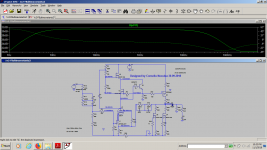
A week ago I started to model a new phono preamp based on 1v2 schematic, going from passive eq network to a current feedback , using the same values used in an AIWA preamp based on a bipolar transistor and an i/v configured op-amp that i described here: https://www.diyaudio.com/forums/analogue-source/328172-modified-aiwa-riaa-fet-phono-preamp.html#post5561157
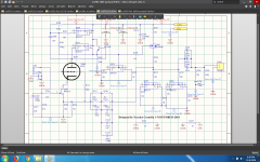
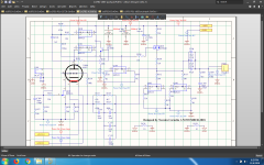
I have here two models working at 150v and 170v dc power supply.The idle current of D3A is a bit different , but the circuit works the same within a small window where bss135 is highly nonlinear actually , which is a bit counter-intuitive. I've used the smd version bsp135 in the real world in the previous passive version instead of the bss135 model and the real nonlinearities of bsp135 are much smaller than what the bss135(through hole version) model predicts .
Unfortunately modelling around this special fet transistor is a pain in the ***, because of that nonlinear window at around 18ma...20.5ma, the exact spot where the d3a valve has the lowest noise.I would have liked to have the d3a working at 18...20ma , but because of the feedback network , when used in closed loop the circuit becomes linear in the nonlinear window and completely nonlinear out of that window and i spent 2 days trying to make it work properly outside the nonlinear window and i couldn't...I'll try to make the original bsp135 model work in lt-spice.That should be the best thing to do for me but i'm no Spice specialist.
Attachments
-
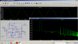
 1v22-fft-50v.png101.2 KB · Views: 81
 -
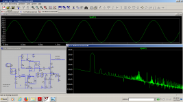
 1v22-fft-0.5v.png103.5 KB · Views: 80
 -
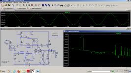
 1v2fft-50v.png100.3 KB · Views: 73
 -
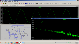
 1v2fft-0.5v.png102.5 KB · Views: 76
 -
 1v22-bode-plot-50v.png67.6 KB · Views: 80
 -
 1v22-bode-plot-0.5v.png68.4 KB · Views: 376
 -
 1v2-bode-plot-0.5v.png68.4 KB · Views: 380
 -
 1v2-bode-plot 50v.png67.9 KB · Views: 439
 -
 1v2-varianta2.png66.7 KB · Views: 458
 -
 1v2-varianta1.png71.9 KB · Views: 474
Last edited:
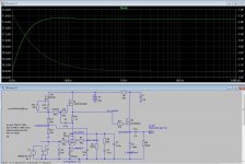
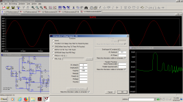
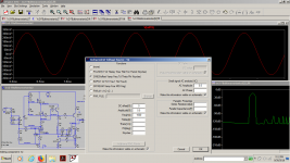
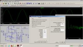
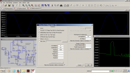
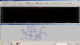
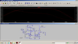
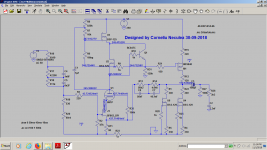
For a month i worked on the last version of 1v2 with feedback, this time using a much cheaper tube, 6n1p.You have attached the sims for two power supply voltages:141vdc and 250vdc.The preamp is perfectly stable within this range , it's also happy with both 11mv and 1.1v on the input for a gain of about 70x and now it has a broader and linear bandwidth than the previous feedback preamp based on D3A which led me to the conclusion that it deserves a full pcb project based on it.I did it before with a D3A but now this tube is way too expensive for most of us.You'll see it in a new set of attachments.For now just finished the schematics.Tommorow i will start the pcb project.
Attachments
-
 1v2FB2-LtSpice-250vdv-11mv-pk-pk.png83.4 KB · Views: 71
 -
 1v2FB2-LtSpice-250vdc-1.1v-pk-pk-inp.png84.8 KB · Views: 87
 -
 1v2FB2-Ltspice-141vdc-11mvpk-pk inp-fft.png86.8 KB · Views: 83
 -
 1v2FB2-LtSpice-141v-1.1v-pk-pk inp-fft.png81.7 KB · Views: 78
 -
 1v2FB2-bodeplot-250vdc-1.1vpk-pk-input-.png69.8 KB · Views: 66
 -
 1v2FB2-Bodeplot-250vdc supply.png69.1 KB · Views: 68
 -
 1v2FB2-Bodeplot-141vdc supply.png70.6 KB · Views: 90
 -
 1v2FB2-bodeplot-141vdc- 1.1V input.png71.5 KB · Views: 149
 -
 1v2FB2-250vdc.png69 KB · Views: 156
Sunday touch my a..ss. I got it all wrong. Still refusing to go with optical coupling...hopefully it's a bit better now! AN70 and AN118 helped a lot .It's not definitive, i need to have a simulation too for the right component values.I was just amazed at how expensive those tiny Coiltronics are , even i big quantity.
Attachments
Last edited:
What a silly complication only to have a noiseless filament! Actually most of the switching noise would come from the filament , not the high voltage and spilling about 7 HOT watts on the second transformer and the linear LT1086 looks like a silly argument when a simple buck converter like lm2596 and a low drop LM2941 can do a great job straight from the 20v supply...The only real problem i see is the fact that the filament is placed in a very sensitive place, in the heart of a cascode! Given the way LT1683 and LT1738 works(controlled slew rate) i'm pretty sure that the switching transistors won't last more than 10 seconds!
I'm absolutely certain that a classic mains transformer, an lm783 and a lm 317 in slow start is actually eating the same power as my dc-dc converter and giving better results ,but you can take this as a funny useless exercise.I really doubt that i'd ever build this dcshit...
I am not aware of a commercial transformer that can give me three secondaries for having the anode HV voltage, a lower voltage for the filament and feedback. If you have any idea, please help me, otherwise i'll have to build it myself.
Last edited:
- Status
- This old topic is closed. If you want to reopen this topic, contact a moderator using the "Report Post" button.
- Home
- Source & Line
- Analogue Source
- 1V2 phono riaa preamplifier