Yes, to get a triangle cut groove we can make a triangle waveform, pass it thru RIAA compensation, then send it to mastering. Their inverse RIAA for cutting would bring it back to our triangle. That's the shape that would be cut.
I'm going to see if I can work out the triangle frequency and amplitude for a given G force at a given track radius.
I'm going to see if I can work out the triangle frequency and amplitude for a given G force at a given track radius.
No, to make a triangle shaped groove we need to make a square-wave waveform and either turn off RIAA during mastering, or reverse-RIAA eq it pre mastering...........Yes, to get a triangle cut groove we can make a triangle waveform, pass it thru RIAA compensation, then send it to mastering. Their inverse RIAA for cutting would bring it back to our triangle. That's the shape that would be cut.
The cut amplitude is the time integral of program waveform level: the cutter's velocity is proportional to instantaneous programme level.
Programme square-wave level determines groove triangle wave 'angle', and square wave rise time determines triangle apex curvature (acceleration or G force).
LD
OK, thanks. Shouldn't be too hard to figure out the waveforms needed - although I might not be the one to do it. ")
This is interesting because I was under the impression that the cutter head is an amplitude device, like a solenoid or a voice coil. In other words, that its position depends on signal amplitude, and not on the signal's rate of change. I wouldn't have thought it a velocity device, like a MM cartridge.
This is interesting because I was under the impression that the cutter head is an amplitude device, like a solenoid or a voice coil. In other words, that its position depends on signal amplitude, and not on the signal's rate of change. I wouldn't have thought it a velocity device, like a MM cartridge.
Programme square-wave level determines groove triangle wave 'angle', and square wave rise time determines triangle apex curvature (acceleration or G force).
LD
I would still suggest that we might explore the linear phase rise time which eliminates the unreproducible discontinuity. The slope at the middle still gives the correct G but it is not preceded by the discontinuity that can have artifacts that obscure things (see Bill's scan of the STR112 jacket).
EDIT - I guess it's time to make some pictures.
Yes, good stuff and that's the way to fly here.I would still suggest that we might explore the linear phase rise time which eliminates the unreproducible discontinuity. The slope at the middle still gives the correct G but it is not preceded by the discontinuity that can have artifacts that obscure things (see Bill's scan of the STR112 jacket).
It raises a very interesting point about playback that hasn't often (if ever) been discussed AFAIK. Whenever stylus acceleration changes, such as from zero in tracing the straight section of a triangular groove to whatever constant value we might choose for the apex of the triangle, there's a rate of change of acceleration. This is known as 'jolt' or 'jerk', and crops up all the time in playback of programme material - it maps on to the instantaneous curvature of programme waveform level.
In the case of a sudden change of acceleration, such as an 'ideal' triangular groove shape with fixed apex curvature, jolt would be huge at the transition, as you say. This isn't what we're trying to test here though, so it's far better to limit jolt in the way you suggest.
In real programme material, stylus jolt is pretty much unexplored, and potentially an interesting performance parameter. But I agree it's better to limit it in the way suggested, for the purpose of this test.
LD
Question out of the blue...
What is the distance, or equivalent distance, between the cutterhead stylus and the fulcrum point that the cutter stylus pivots about? Is the motion of the cutter stylus in a plane defined by the VTA, or is it an arc whose curvature is defined by a cutter stylus "shaft length"? If the latter, then how concerned should we be about the tracing distortion created by the curvature of the playback stylus arc not matching the the curvature of the cutter stylus arc? IOW, does the playback stylus shaft length need to match the cutter sylus shaft length for minimum tracing distortion?
Ray K
Last edited:
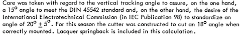
Ray, in the documentation for the Neumann cutting heads sit ay the angle has been calculated for 15 degrees. That includes the effect of vinyl spring-back. I'll post the exact test.
I also found some good information on groove curvature and acceleration, as well as driver currents. Will post all that in a bit.
I also found some good information on groove curvature and acceleration, as well as driver currents. Will post all that in a bit.
Ray, in the documentation for the Neumann cutting heads sit ay the angle has been calculated for 15 degrees. That includes the effect of vinyl spring-back. I'll post the exact test.
I also found some good information on groove curvature and acceleration, as well as driver currents. Will post all that in a bit.
I get all of that but you're missing the gist of my question.
Ray K
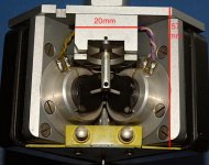
From Calibration Instructions of SX74 cutter head.
From the Neumann manuals.
An 8 Amp current produces and acceleration of 47,500 m/s2. This acceleration brings with it a groove curvature which is dependent on the linear groove velocity.
ρ=V2/b

(not sure of the symbol, I have used rho. Please let me know)
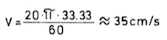
An example may serve to illustrate this better: recording at a groove diameter of 20 cm (8 in.) and at 33 1/3 rpm, the following occurs:
v=20*π*33.33/60 ≈ 35 cm/s
The groove curvature derived from this is:
ρ=35*35/4.75*106 ≈ 2.6µ
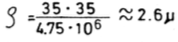
If, in this case the groove curvature is smaller than that of the stylus, the playback distortion increases steeply. If the curvature is not to be smaller than that of a stylus of, for example, 15u (0.6 mils) radius, the boundary acceleration resulting would be:
b=v2/∂ = 35*35/1.5*10-3 ≈ 8150 m/s2
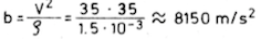
Since, for a constant current, a cutter produces constant acceleration independent of the frequency, the current would, in this case, be limited to approximately 1.4A
I hope this will help with the groove geometry need.
From the Neumann manuals.
An 8 Amp current produces and acceleration of 47,500 m/s2. This acceleration brings with it a groove curvature which is dependent on the linear groove velocity.
ρ=V2/b
(not sure of the symbol, I have used rho. Please let me know)
An example may serve to illustrate this better: recording at a groove diameter of 20 cm (8 in.) and at 33 1/3 rpm, the following occurs:
v=20*π*33.33/60 ≈ 35 cm/s
The groove curvature derived from this is:
ρ=35*35/4.75*106 ≈ 2.6µ
If, in this case the groove curvature is smaller than that of the stylus, the playback distortion increases steeply. If the curvature is not to be smaller than that of a stylus of, for example, 15u (0.6 mils) radius, the boundary acceleration resulting would be:
b=v2/∂ = 35*35/1.5*10-3 ≈ 8150 m/s2
Since, for a constant current, a cutter produces constant acceleration independent of the frequency, the current would, in this case, be limited to approximately 1.4A
I hope this will help with the groove geometry need.
Attachments
I guess "we" don't but maybe someone does. It's worth researching.So the answer is "we don't know"?
Here is something I found, tho it's not what you are asking it might help.
Attachments
No, didn't miss it - just saying that the cutterhead documentation I've seen does not address that, just the angle of the cut.
I have always assumed, perhaps mistakenly that all that mattered was the angle of the cut at the precise point where the cut was occurring. I don't know how many cutting geometries there are and how the geometry of the cutter stylus itself would impact this. (I have been lead to believe it is not all that similar in some respects to the geometry of the styli we use for playback, it is a chisel after all.)
Practically speaking we don't have control over these parameters either in disk mastering or playback. We don't control what happens at the cutter and no one here probably has remotely similar playback hardware (arms and cartridges).
Finally got a sec amidst the holiday whirlwind... here Pano as promised, v1.

Where are things presently? It's been a while since I've scanned the thread.
As far as the cover I took liberties with wording just to get something moving... just a first stab.
Thoughts re: title and tagline?
For the back presumably there'd be:
Tracklist and extended track info
Thank you / call out to particularly helpful folks
Maybe a little blurb about how it came to be / what the goals were
I've also seen walkthroughs / procedural info sometimes on the back cover and sometimes on the insert. I think the back cover would be most useful.. I always wind up misplacing or damaging inserts or sometimes they go undiscovered entirely. If back cover is the consensus that will be a lot of text to jam on there.
If someone could assist in getting to me just some tentative information so that I can get a feel for the layout it would be appreciated. I am assuming we are still a ways out but it's nice to make progress where you can.
Last edited:
Wow! That came out about 100x better than I had imagined. Bravo!
We are getting close to a definitive track list, then it will be test signals and financing the project.
Documentation will be crucial, as you mention. We need to cram what we can onto the back cover, with a URL to more info and software.
We are getting close to a definitive track list, then it will be test signals and financing the project.
Documentation will be crucial, as you mention. We need to cram what we can onto the back cover, with a URL to more info and software.
Wow! That came out about 100x better than I had imagined. Bravo!
We are getting close to a definitive track list, then it will be test signals and financing the project.
Documentation will be crucial, as you mention. We need to cram what we can onto the back cover, with a URL to more info and software.
Thanks Pano. It’s just a beginning. Fine tuning later.
My only suggestion regarding the url is that it’s hosted somewhere as permanent as it gets. Also short is obviously preferential. Many dead links out there and test records tend to stick around for a while.
~12x12 is a lot larger than one might assume at first. I deal with a lot less “friendly” dimensions.
That being said I don’t want it to be grueling for those without the best vision... have to consider audience.. ( in the burning amp photos I’ve seen I notice a lot of squinting going on! ;-) )
If you do a gatefold or an insert (cheapest option) you can increase legibility drastically. While I don’t love inserts I can’t deny their utility and cost effectiveness.
- Home
- Source & Line
- Analogue Source
- Test LP group buy