Hi,
I recently completed my LM3886 chipamp and there's a bit of space left in the box that i think I could squeeze a phono stage into.
I'm going to build a version of the passive eq phono amp described in section 3.1 of this TI application note. The only deviations I'm going to make to the circuit are to reduce the gain of U1 and use a 47R and 300pF across the inputs as I use a MM cartridge.
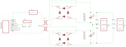
The amplifier circuit includes U4 & 5 to 'flatten' impedance on the supply rails so I assume I can go for a pretty simple power supply (schematic attached), I've based the design on the following components:
Trafo
Bridge Rectifiers
Caps
My question is does this look like a sensible choice? I'm pretty new to this so I'd be grateful for any advice.
I recently completed my LM3886 chipamp and there's a bit of space left in the box that i think I could squeeze a phono stage into.
I'm going to build a version of the passive eq phono amp described in section 3.1 of this TI application note. The only deviations I'm going to make to the circuit are to reduce the gain of U1 and use a 47R and 300pF across the inputs as I use a MM cartridge.
The amplifier circuit includes U4 & 5 to 'flatten' impedance on the supply rails so I assume I can go for a pretty simple power supply (schematic attached), I've based the design on the following components:
Trafo
Bridge Rectifiers
Caps
My question is does this look like a sensible choice? I'm pretty new to this so I'd be grateful for any advice.
Attachments
The amplifier circuit includes U4 & 5 to 'flatten' impedance on the supply rails
so I assume I can go for a pretty simple power supply.
You will want regulation after the filter capacitor for a phono preamp.
Thanks, I'll look into options for regulating and use of CRC... as it's in the same box as the chipamp it would be nice if I could use the 2x25V 300VA transformer that's already in there. Unfortunately I get 37VDC after the regulator with that which rules out a linear regulator and I've no experience with switching regulators.
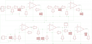
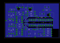
As for layout of the amplifier, I've had a stab by making a direct copy of the TI schematic in eagle (which I need to update the gain and input R&C for). There's no local decoupling... ideally I'd like to experiment but I need to work out how I can do that.
As for layout of the amplifier, I've had a stab by making a direct copy of the TI schematic in eagle (which I need to update the gain and input R&C for). There's no local decoupling... ideally I'd like to experiment but I need to work out how I can do that.
Attachments
Unfortunately I get 37VDC after the regulator with that which rules out a linear regulator and I've no experience with switching regulators.
(assuming you meant 'rectifier' here where you wrote 'regulator')
If you choose a variable regulator like the venerable old LM317T then 37V input isn't a problem if your output is 15V (or so). The regulator is specified for a maximum input-to-output difference of 40V. Shorting the output might cause you to exceed that difference though - I'd put some resistors in series (as already suggested) prior to the reg's input terminal to mitigate the risk.
(assuming you meant 'rectifier' here where you wrote 'regulator')
Doh!.. Yep I meant rectifier. Thanks I'll take a look at those regulators.
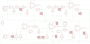
As for layout of the amplifier, I've had a stab by making a direct copy of the TI schematic in eagle
(which I need to update the gain and input R&C for). There's no local decoupling.
The supply buffers have a 1uF capacitor at each output. Arrange the placement of the buffer and capacitor
to be close to the supply pin of the RIAA op amp. Also add a parallel 0.1uF - 0.01uF directly at the supply pin.
The supply buffers have a 1uF capacitor at each output.
Yes... of course, thanks. I was looking for decoupling caps at each of the op amps and missed the obvious. I'll shuffle things around and see how close I can get them.
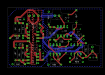
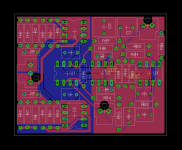
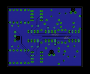
Thanks for the advice so far... I've reworked the schematic & layout as suggested by adding two pours for the power supply on the bottom layer and moving things around to get the RIAA op amp closer to the buffers & caps. Does this look like an improvement?
Attachments
I've reworked the schematic & layout as suggested by adding two pours for the power supply
on the bottom layer and moving things around to get the RIAA op amp closer to the buffers & caps.
I'd place the op amps in line: U1, U2, U3 (servo). Then place the buffers U4/U5 above and below U1/U2,
with their output capacitors between the buffers and U1/U2. A very direct supply connection is necessary.
Then route these power supply connections first, before adding more parts. Something like this:
--U4--------
--C4--------
U1--U2--U3
--C3--------
--U5--------
Last edited:
Thanks rayma, I'll have a go at re-jigging the layout. I find it difficult to know what to trade off in the design: keeping the feedback loop short; separating the supply voltage from the signal etc. When I was doing the layout for the LM3886 it was (eventually) possible to separate the DC from the signal, decouple right up against the IC and keep the feedback loop short... with the five op amps in this design it's not so straight forward.
I find it difficult to know what to trade off in the design: keeping the feedback loop short;
separating the supply voltage from the signal etc.
Several tries are usually necessary to approximate a good layout. Always start with the most critical paths,
i.e. the power supply and minimizing the op amp's inverting input connection lengths.
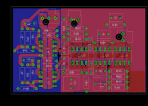
That sounds like good advice. I've had another go, I think I could still move U1,2&3 over to the left a bit more to get U2 closer to the supply caps but I'm a bit concerned about putting more distance between U1, the input and the RIAA network. Plus I'm not totally happy with the pours but it seems like a step forward.
Attachments
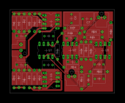
I'm a bit concerned about putting more distance between U1, the input and the RIAA network.
Plus I'm not totally happy with the pours but it seems like a step forward.
Keep playing around with it, you'll get there.
I guess U4 and U5 are meant to filter the supplies. I'm not sure whether they will remain stable with C4 and C3 as a load. If C4 and C3 are ordinary run-of-the-mill electrolytic capacitors, their effective series resistance will probably help to keep U4 and U5 stable, otherwise you may have to insert small resistors between U4/U5 and C4/C3.
By the way, the LM317 has a high-voltage version, the LM317HV, that can handle 60 V of input voltage (even with shorted output). The LM337 also has an HV version, but the LM337HV is only meant for -50 V. (The LM317 also needs the ESR of the decoupling capacitors to remain stable, so don't use it with only film or ceramic decoupling.)
I don't understand your remark about 47 ohm in the first post, was that simply a typo for 47 kohm?
Noise-wise the LME49710 is not the best choice for phono amplifiers. Its noise is specified as 2.5 nV/sqrt(Hz) of equivalent input noise voltage density and 1.6 pA/sqrt(Hz) of equivalent input noise current density. The noise voltage is a bit high for moving coil and the noise current is a bit high for moving magnet.
Hi MarcelvdG,
I think that the following extract from application note is reference to U4 & U5:
"the power supply rails must present a low and more importantly flat impedance across the audio bandwidth to preserve the audible spectral balance and overall integrity of the input signal. The PSRR of the LME49710/LM4562 is outstanding across the full audio bandwidth and therefore is highly immune to power supply impedance discontinuities. However, given the low level signals provided from moving coil phono cartridges, the effect is more pronounced and therefore the impedance of the supply rails is addressed in this application."
For the caps I plan to use Wima MKS2
Thanks for pointing out the LM317HV, I'll take a look. I think I'll experiment with the PSU, I can't decide whether the inefficiencies of regulating down from 37V outweigh the space / cost of including an extra trafo.
I did mean 47k (there does appear to be an error in the application note too as it refers to 47 Ohm in section 3.3)
I think I'll carry on with this chip for now and use it to experiment... I'm learning as I go (if that's not obvious ). I am however interested in other options... do you have a suggestion for a better performing op amp that would require a circuit of similar simplicity/complexity?
I think that the following extract from application note is reference to U4 & U5:
"the power supply rails must present a low and more importantly flat impedance across the audio bandwidth to preserve the audible spectral balance and overall integrity of the input signal. The PSRR of the LME49710/LM4562 is outstanding across the full audio bandwidth and therefore is highly immune to power supply impedance discontinuities. However, given the low level signals provided from moving coil phono cartridges, the effect is more pronounced and therefore the impedance of the supply rails is addressed in this application."
For the caps I plan to use Wima MKS2
Thanks for pointing out the LM317HV, I'll take a look. I think I'll experiment with the PSU, I can't decide whether the inefficiencies of regulating down from 37V outweigh the space / cost of including an extra trafo.
I did mean 47k (there does appear to be an error in the application note too as it refers to 47 Ohm in section 3.3)
I think I'll carry on with this chip for now and use it to experiment... I'm learning as I go (if that's not obvious
). I am however interested in other options... do you have a suggestion for a better performing op amp that would require a circuit of similar simplicity/complexity?OK, if you got that supply circuit from an application note, whoever wrote the note must have checked the stability.
When you look only at the noise matching to a moving-magnet cartridge, the good old NE5534A does very well, as do some modern JFET-input op-amps, like the OPA1641 (or 1642 or 1644), or the OPA1652 (or 1654).
To compare op-amps with different equivalent input noise current and noise voltage densities, you need to know the exchange rate between the two. If the source impedance were constant, that would simply be the source impedance: multiply the equivalent input noise current density by the source impedance and you have calculated what equivalent input noise voltage density would give the same amount of output noise.
The impedance of a moving-magnet cartridge is, however, far from constant over the audio band. As a rule of thumb, you can take the cartridge impedance at 3852 Hz. With a typical 500 mH, 1 kohm cartridge, the impedance at 3852 Hz is about 12 kohm. So each pA/sqrt(Hz) roughly counts as 12 nV/sqrt(Hz).
LME49710:
current 1.6 pA/sqrt(Hz) -> has as much impact as 19.2 nV/sqrt(Hz)
voltage 2.5 nV/sqrt(Hz)
Total is the root of the sum of the squares: 19.36 nV/sqrt(Hz)
NE5534A:
current 0.4 pA/sqrt(Hz) -> has as much impact as 4.8 nV/sqrt(Hz)
voltage 3.5 nV/sqrt(Hz)
Total is the root of the sum of the squares: 5.94 nV/sqrt(Hz)
OPA164X:
current 0.0008 pA/sqrt(Hz) -> has as much impact as 0.0096 nV/sqrt(Hz)
voltage 5.1 nV/sqrt(Hz)
Total is the root of the sum of the squares: 5.1 nV/sqrt(Hz)
OPA165X:
current 0.003 pA/sqrt(Hz) -> has as much impact as 0.036 nV/sqrt(Hz)
voltage 4.5 nV/sqrt(Hz)
Total is the root of the sum of the squares: 4.5 nV/sqrt(Hz)
To put these figures into perspective, the 47 kohm termination resistor injects 0.5869 pA/sqrt(Hz) of noise current into the cartridge. According to my rule of thumb that corresponds to 7.04 nV/sqrt(Hz). The thermal noise of the cartridge itself increases this to around 10 nV/sqrt(Hz), so whenever the result of the calculation of the op-amp noise is below 10 nV/sqrt(Hz), it contributes less to the total noise than the termination resistor and the cartridge do, even when there is no record playing.
Please keep in mind that I assume a cartridge inductance of about 500 mH. Many cartridges have inductances of this order of magnitude, but there are also models that have far less inductance and are therefore less sensitive to noise current.
Last edited:
I just looked up the OPA165 and can only find it in a SMD package. I've not tried surface mount
soldering before - maybe I should give it a go.
An SO-8 package is easy, just tack one corner first.
- Status
- This old topic is closed. If you want to reopen this topic, contact a moderator using the "Report Post" button.
- Home
- Source & Line
- Analogue Source
- LME49710 Phono Stage