Hi folks, this is my first post on DIY audio. I can't believe I'm just now discovering this forum, because it would've been the perfect place to get help on this tape scratching device I've been developing for the past few years. If you're curious, here's a video of my previous prototype.
Anyway, I'm working on a new prototype the will be fully self-contained, and that means not using four mic preamps to amplify the playhead signal anymore. So far I've been using these little stereo preamp kit boards I found on eBay, but the sound is a bit thin, so I've been looking for a solution that is specifically for audio tape. I just ordered these playhead preamp IC's which seem perfect for my needs. I'm a little leery about working with individual IC's, as my circuit-building experience is somewhat limited, but by the looks of this PDF I found, they look very simple... almost too simple! Could it really be this easy? Or am I going to have to buy a bunch of other components to get them to work for my purposes?
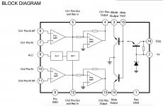
I'm not sure about some of the terminology in the PDF, but here's how I think it would work: If I'm using a two-channel playhead, I'd route the playhead's two hot leads to pin 7 and 10, and the ground/shield would go to pins 6 and 11. And then for the line out, 5 and 12 would be the two hot pins, and 9 is the ground/shield. And for the power, I'm guessing positive is 16 and negative is... maybe 8? Am I in the ballpark?
Thanks!
Anyway, I'm working on a new prototype the will be fully self-contained, and that means not using four mic preamps to amplify the playhead signal anymore. So far I've been using these little stereo preamp kit boards I found on eBay, but the sound is a bit thin, so I've been looking for a solution that is specifically for audio tape. I just ordered these playhead preamp IC's which seem perfect for my needs. I'm a little leery about working with individual IC's, as my circuit-building experience is somewhat limited, but by the looks of this PDF I found, they look very simple... almost too simple! Could it really be this easy? Or am I going to have to buy a bunch of other components to get them to work for my purposes?
I'm not sure about some of the terminology in the PDF, but here's how I think it would work: If I'm using a two-channel playhead, I'd route the playhead's two hot leads to pin 7 and 10, and the ground/shield would go to pins 6 and 11. And then for the line out, 5 and 12 would be the two hot pins, and 9 is the ground/shield. And for the power, I'm guessing positive is 16 and negative is... maybe 8? Am I in the ballpark?
Thanks!
Attachments
Tape preamp, like mag phono preamp, has HUGE bass boost. This is why a "Mike" (flat) preamp sounds "thin".
I can not make out that PDF, not so I would try to build it.
That eBay preamp "could" be modified. Replace one resistor with one C and two R. But without a schematic, it is a headscratcher to know what and where. And working with SMD parts is a special skill.
Traditionally we made tape preamps from phono preamps. Sometimes a switch to select phono or tape EQ.
LM381 was a less-popular chip made for such use. Tape preamp is the first example in the datasheet. LM381 has gone out of regular distribution, but eBay sellers claim to have them.
Hi PRR, thanks for your reply. That's useful info!
You couldn't make out the PDF? Did the link not work for you? You should be able to go to the link and then just click on "page 1." I also attached an image that I grabbed from the PDF. You can full-screen it if it's hard to read. I'm eager to experiment with these IC's, and I'd really appreciate any insights on how to wire them. However, I'll add that it was only 10 bucks for five of them, so if I burn out a few, no big deal!
You couldn't make out the PDF? Did the link not work for you? You should be able to go to the link and then just click on "page 1." I also attached an image that I grabbed from the PDF. You can full-screen it if it's hard to read. I'm eager to experiment with these IC's, and I'd really appreciate any insights on how to wire them. However, I'll add that it was only 10 bucks for five of them, so if I burn out a few, no big deal!
Well, tonight I tried wiring it up just to test the preamp function, but sadly, I couldn't get any sound. I'm sure I probably wired it wrong. I'd be super grateful if someone could take a look at this and tell me where I went wrong:
12v DC to pins +16 and -9
Two-channel playhead to pins 7/6 and 10/11
Left channel output to pins 5 and 9
Right channel output to pins 12 and 9
12v DC to pins +16 and -9
Two-channel playhead to pins 7/6 and 10/11
Left channel output to pins 5 and 9
Right channel output to pins 12 and 9
Your supplies seem to be OK.
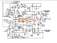
I suspect your problems will come down to the way you have connected and biased the inputs. There are some really poor circuit diagrams on the web that look to be lifted from cassette recorder manuals.
Look at this one.
One side of the head goes to ground. (the switch on the head is for play/record as the chip functions as a record amp as well to drive the head)
The other side is AC coupled (together with a series resistor) into the + opamp input.
There is also a 1000pF cap from + input to ground. That is for high frequency filtering.
The - input is configured as a normal opamp would be and two resistors set the gain, R1 and R4. There is connecting a blob missing on R1 (look at the other channel below).
The cap C6 is essential to preserve the DC conditions.
All other components in the feedback network determine the equalisation curve which is something you may not need or may not need to be exact.
The output from the first opamp must be AC coupled to the next stage.
So its really a standard opamp configuration apart from the + input being self biasing. Note that there are errors on that diagram. The lower channel has the opamp inputs incorrectly shown.
Attachments
Well, tonight I tried wiring it up just to test the preamp function, but sadly, I couldn't get any sound. I'm sure I probably wired it wrong. I'd be super grateful if someone could take a look at this and tell me where I went wrong:
12v DC to pins +16 and -9
Two-channel playhead to pins 7/6 and 10/11
Left channel output to pins 5 and 9
Right channel output to pins 12 and 9
Note that pin 1 needs to be grounded along with pin 9.
Also you need to build what looks pretty much like the test circuit and replace that switch S2 with the tape head. (One channel of the head connects to one of the 2.2K resistors and ground) Other changes may be required.
Note ....... Other changes may be required.
I could not find a ready-bake just-preamp plan for this obscure chip. Which seems to be much more than just a preamp.
LM381 may be harder to source but had beautiful documentation.
AND8177 page 8 has a basic dual-supply '5532 preamp with RIAA/NAB switch. Throw the switch to NAB, replace switch with jumper, and leave-off the 2R 2C on the RIAA side. The "16K" value depends on tape speed and may want adjustment to balance >3KHz against the lows-mids.

I can confirm Mooly's comments about the LM381. Long ago I had this strange predilection for making cassette players with old Philips cassette recorders that I installed a stereo head in and scratch built transistorized tape pre-amps. For my last I thought it would be grooovy to design one with the LM381. The first chip burned up, (probably oscillating) the second was OK, but sounded neither as good as the discrete and was also significantly noisier. It got replaced with a discrete design instead..
Note that you can use an 5532 with the same circuit recommended for the 381 and it should work.
Note that you can use an 5532 with the same circuit recommended for the 381 and it should work.
Note that you can use an 5532 with the same circuit recommended for the 381 and it should work.
IIRC, the '381 had self-bias for single-supply operation. This would have to be re-thought to work in the dual-supply '5532 plan I linked.
Never had problem with '381 in simple tasks. Never did compare one to the finest preamps ever made.
- Status
- This old topic is closed. If you want to reopen this topic, contact a moderator using the "Report Post" button.
- Home
- Source & Line
- Analogue Source
- Tape playhead preamplification