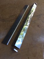
I am in the early throes of building an air bearing tonearm similar to the terminator design.
So far I have made a prototype using aluminium angle and flat bar. I have tested using a hi flow aquarium air pump.
The terminator design only uses a 285 L/hr pump to achieve lift. Mine is using a lot more than that and is only just doing the job! Admittedly I have only taped the parts together so far and would bond all parts together th make an air tight seal.
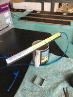
I have fed air in from one end as per photo and I get a constant hiss of air coming out of the holes. I thought I might be able to reduce this by countersinking the holes from inside but this has not helped much.
I have also made a triangular section that fits inside the aluminium with two grooves machined down the length adjacent to the holes. Basically i have reduced the volume of air inside the chamber to be more directed to the holes. Not a great deal of change there!
I see on a lot of the threads that pressure of between 50 and 70 odd psi is used in other setups.
I would appreciate any advice/feedback with this as I am keen to get the carriage floating properly.[/ATTACH][/ATTACH]
So far I have made a prototype using aluminium angle and flat bar. I have tested using a hi flow aquarium air pump.
The terminator design only uses a 285 L/hr pump to achieve lift. Mine is using a lot more than that and is only just doing the job! Admittedly I have only taped the parts together so far and would bond all parts together th make an air tight seal.
I have fed air in from one end as per photo and I get a constant hiss of air coming out of the holes. I thought I might be able to reduce this by countersinking the holes from inside but this has not helped much.
I have also made a triangular section that fits inside the aluminium with two grooves machined down the length adjacent to the holes. Basically i have reduced the volume of air inside the chamber to be more directed to the holes. Not a great deal of change there!
I see on a lot of the threads that pressure of between 50 and 70 odd psi is used in other setups.
I would appreciate any advice/feedback with this as I am keen to get the carriage floating properly.[/ATTACH][/ATTACH]
Attachments
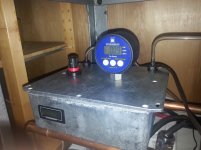
Just as a point of reference I use a Terminator Tonearm and the Rena 400 pump is way more than one needs in practice. I have a needle valve control on the feed line and it floats fine at as low as 0.6-1.0 PSI. I have mine set at 0.8 PSI. I think you are on the right track with the needle holes.
The first one I made I made a box section glueing all the parts with a 2 part epoxy. I think there were two reasons why it was unsuccessful 1. the holes were way too big and the air chamber was too big also.
The second one I made is like the Terminator where I sandwiched to pieces of angle together and sealed the edges with epoxy. The holes are now 0.3mm and the air chamber has been drastically reduced.
The second one I made is like the Terminator where I sandwiched to pieces of angle together and sealed the edges with epoxy. The holes are now 0.3mm and the air chamber has been drastically reduced.
Right....sandwiching two pieces of angle which forms the air chamber, the top of sandwich has the holes, and a third top angle which holds the carrier slides along that on a cushion of air.
Its the ends and sides of the sandwich that I am working out......
My idea would be to have a 4th sacrifical piece of angle. Cut two lengths about half an inch off of the end for what would sit at each end of the sandwich. Cut about a half inch off of the sides length ways of the sacrificial piece which would sit between the sandwich pieces at the sides. Smooth all of the cuts and epoxy together.
Im thinking this should make a pretty uniform air chamber.
Im also thinking that depending on the quality of the angle that a small plate will need to be affixed to the bottom section where the air input will be screwed in. This would give more thickness for threading the hole to screw it in.
Polishing the slide and top piece prior to drilling to make a better interface.....I have heard of people using tooth paste to do this, but I am thinking that yellow bar and then a very fine mirror grinding grit would be better. You really want a very smooth surface for those two pieces.
Thoughts?
I would use the grit that is used to polish telescope mirrors. 25 micron grit mixed with oil would work well.
There are also sellers on ebay who sell various grit size polishing paste.
Im not sure that I would anodize the angles though. You would be adding a coating to the interface of the two pieces of metal.
Oh, drill first before lapping. Drilling will deform the metal slightly and the lapping will solve that.
....I am in the early throes of building an air bearing tonearm similar to the terminator design. ......
.... any progress ...... ?
- Status
- This old topic is closed. If you want to reopen this topic, contact a moderator using the "Report Post" button.
- Home
- Source & Line
- Analogue Source
- diy air bearing tonearm build