Bill,This is one of those off but on topic questions, but as the plots are here seemed the best place to put it. As part of the planning for the integration of my various phono projects I had a re-mull over HPF and noticed that Self has produced PCBs for his 'deviynliser'. In effect this is very similar to a mastering elliptic filter in that it gives very steep roll off for side information and leaves mid untouched. Now although the damage has already been done, and damping is the best way in a undamped system there is still considerable energy in the subsonic region that flaps woofers and eats up ADC headroom so I think its worth the experimentation to see if it's a useful thing to be able to patch in?
Sadly this now means I need 3 inserts in my analog front end. Four if I get the coils on one of my cartridges rotated 45 degrees to give M-S output rather than L-R")
If I may give you some advise, Self assumes for the devyniliser that the subsonic signals it should eliminate are perfectly out of phase and of equal amplitude, both only true in an ideal world.
The slightest deviations already leads to less effective suppression and a large difference in FR between both channels.
The purpose of a Rumble or subsonic filter is to protect your speaker system, so why only eliminate out of phase subsonics ?
If you want to test the effectiveness, switch your amp to Mono and watch your subwoofers.
When they stop flapping, the devyniliser might be a solution for you.
A far better solution to my opinion is Selfs rumble filter in Linear Audio 12 with eliptical fiters. A really clever design, with a fantastic cut off curve, -0,5dB@20Hz and -70dB@10Hz for a 5th or 6th order filter, while still keeping the group delay almost within the 20msec that Holman once considered to be the threshold for a rumble filter.
Hans
Well I don't have a sub in the system (yet) so the flapping is only a theoretical issue, but the waste of headroom seems to be worth investigation. Given that, looking at the plots of George's system the L-R subsonics were nearly 10dB higher than L+R then I saw the possibility of a 'quick win' without fretting about filtering out actual signal*.
Thank you for reminding me about his eliptical version. I note that is available for individual download so I'll grab that for a read.
*Yes I know in this age of ADC with 19-21 ENOB gaining an extra bit can seem hardly worth the worry
Thank you for reminding me about his eliptical version. I note that is available for individual download so I'll grab that for a read.
*Yes I know in this age of ADC with 19-21 ENOB gaining an extra bit can seem hardly worth the worry
Hi Niffy,
I'm a bit confused by your graph. The Am/Cart resonance is a second order system.
A second order system, whatever the damping or the Q is, drops down after some time with 40dB/decade.
Yet in your graph between 100Hz and 1000Hz it is only 10dB.
Could it be the scale is wrong ?
Hans
Hi Hans,
Well spotted. I don't know how I missed that. I'll have to check the equation I used. I'm think I might have used 10log(x) rather than 20log(x) but that would still have only given a 20dB/decade slope. Possibly typed the right equation into excel incorrectly.
Oops
Niffy
Hi Hans,
I've double checked my calculations and I had indeed used the wrong log. School boy error. The rest of my calculations are actually correct. The graph just showed all the x axis values to be half of what they should have been.
With a spring-mass-damper system the response does drop down at 40dB/decade but only if it is completely undamped. If the system is critically damped the response drops down by 20dB/decade. Unless the level of damping is very low the response will still drop down at about 20dB/decade. A damping ratio of just 0.005 is required to increase the drop to 25dB/decade.
My assertion that higher effective mass holds the cartridge with significantly less movement at low frequencies is valid.
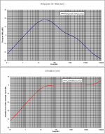
I've redone the graph with the correct vertical scale. This time I've shown the responses for arms tuned to 8hz and 15hz as this covers the largest range for vertical effective masses.

I modelled the cartridge as having a compliance of 15um/mN and a suspension with a damping coefficient of 0.2. Both reasonably typical I believe. The 8hz would have had an effective mass of 26.4g and the 15hz of 7.5g. At 50hz the motion of the cartridge for the 8hz arm is 11.5dB less than for the 15hz arm. That's about a quarter the movement. With an arm tuned to 10hz cartridge body movement relative to the stylus is only -24dB. That means the cartridge is moving 1/16 the amount the stylus moves.
Hi all,
It may seem off topic to mention this in this thread but I believe that it is relevant. When designing I like to take a holistic approach, working out how each aspect effects all the others. All to often a designer will pursue completely eliminating problem A only to make problem B worse and introduce problem C.
For instance reducing the effective mass in order to raise the resonant frequency and in doing so improve speed stability seems good. However a lower effective mass arm will have to be more lightweight in is build and therefore less rigid leading to greater bending modes resonances at higher frequencies. Also lower effective mass, as previously mentioned, holds the cartridge less still at low frequencies.
Likewise the brush on the shure cartridges can improve damping but, as mentioned in a previous post, can effect tracking force on warps and feed vibration into the cartridge. I do recall it being popular to completely remove the brush for this reason. The Townsend trough is a much better (and expensive) option. Can't wait to see a trough no trough comparison.
Niffy
I've double checked my calculations and I had indeed used the wrong log. School boy error. The rest of my calculations are actually correct. The graph just showed all the x axis values to be half of what they should have been.
With a spring-mass-damper system the response does drop down at 40dB/decade but only if it is completely undamped. If the system is critically damped the response drops down by 20dB/decade. Unless the level of damping is very low the response will still drop down at about 20dB/decade. A damping ratio of just 0.005 is required to increase the drop to 25dB/decade.
My assertion that higher effective mass holds the cartridge with significantly less movement at low frequencies is valid.
I've redone the graph with the correct vertical scale. This time I've shown the responses for arms tuned to 8hz and 15hz as this covers the largest range for vertical effective masses.
I modelled the cartridge as having a compliance of 15um/mN and a suspension with a damping coefficient of 0.2. Both reasonably typical I believe. The 8hz would have had an effective mass of 26.4g and the 15hz of 7.5g. At 50hz the motion of the cartridge for the 8hz arm is 11.5dB less than for the 15hz arm. That's about a quarter the movement. With an arm tuned to 10hz cartridge body movement relative to the stylus is only -24dB. That means the cartridge is moving 1/16 the amount the stylus moves.
Hi all,
It may seem off topic to mention this in this thread but I believe that it is relevant. When designing I like to take a holistic approach, working out how each aspect effects all the others. All to often a designer will pursue completely eliminating problem A only to make problem B worse and introduce problem C.
For instance reducing the effective mass in order to raise the resonant frequency and in doing so improve speed stability seems good. However a lower effective mass arm will have to be more lightweight in is build and therefore less rigid leading to greater bending modes resonances at higher frequencies. Also lower effective mass, as previously mentioned, holds the cartridge less still at low frequencies.
Likewise the brush on the shure cartridges can improve damping but, as mentioned in a previous post, can effect tracking force on warps and feed vibration into the cartridge. I do recall it being popular to completely remove the brush for this reason. The Townsend trough is a much better (and expensive) option. Can't wait to see a trough no trough comparison.
Niffy
Hans: I downloaded the Self paper last night and gave it a preliminary read. I'll need to read it a few more times! It's almost verging on a heroic effort there, which means I'll have to build it one day. 7 op-amps per channel will I think give some palpitations
Niffy: I sort of agree with you on the mass/rigidity side, which is why I have aquired an SME 3009 SIII for experiments. This is super light, but uses nitrided titanium so is nicely stiff as well. I look forward to time to test it out.
Niffy: I sort of agree with you on the mass/rigidity side, which is why I have aquired an SME 3009 SIII for experiments. This is super light, but uses nitrided titanium so is nicely stiff as well. I look forward to time to test it out.
Interesting. As an experiment I loaded one of George's rips of 'O fortuna' and messed around with filtering to see if my conjecture made any sense. So far I have learned that I can't drive audacity . I had assumed that applying a steep HPF at around 20Hz should be visible as a small drop in program level. Trying this I can see some increases in peaks but no reduction elsewhere. I need to look at a quieter section. I fear the conclusion will be I'm using the wrong tool for the job!
. I had assumed that applying a steep HPF at around 20Hz should be visible as a small drop in program level. Trying this I can see some increases in peaks but no reduction elsewhere. I need to look at a quieter section. I fear the conclusion will be I'm using the wrong tool for the job!Yes, I realised late last night that, when Self mentioned the infrasonics being only 10dB below signal level that meant the very quiet passages! I have 5PEQ available on the miniDSP input channels so in theory could implement something similar digitally. I just now need to get my head around if there is any benefit in terms of reduction of FM artifacts.
Interesting. As an experiment I loaded one of George's rips of 'O fortuna' and messed around with filtering to see if my conjecture made any sense.
Bill
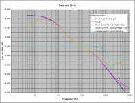
For these recordings I have used the Hagerman Bugle RIAA preamplifier which incorporates the IEC amendment to the original RIAA spec.
Thus there is already a low freq roll off in there.
Att. 1 is the freq response of the M97+Bugle (measurement, 60kOhm// 288pF loading)
Att. 2 is the gain plot of the M97+Bugle (sim) and the deviation from the original RIAA curve (sim)
George
Attachments
Equalization (harwired or softw implemented) can’t do anything with FM.I have 5PEQ available on the miniDSP input channels so in theory could implement something similar digitally. I just now need to get my head around if there is any benefit in terms of reduction of FM artifacts .
George
Hi,The Townsend trough is a much better (and expensive) option. Can't wait to see a trough no trough comparison.
Niffy
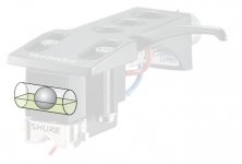
Instead of trough, why would a very small tuned mass damper at cartridge not work ? Kind of tiny weight attached to cartridge with proper compliance spring or something.
Regards.
Yes Ray K,
that type which you had posted earlier. but on small scale. OR with viscous fluid like pic attached. And shown in following video link
Tuned mass damper
Regards
Attachments
Equalization (harwired or softw implemented) can’t do anything with FM.
George
Yes, but you have to get your head around that
. I've always just accepted it, and then I tried thinking about it and my head hurt!Yes Ray K,
that type which you had posted earlier. but on small scale. OR with viscous fluid like pic attached. And shown in following video link
Tuned mass damper
Regards
The damper as shown in the diagram would only damp lateral motion. It would have very little effect in damping vertical motion which is the direction the damping would be mainly required in.
Niffy
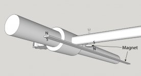
Actually, I am thinking of building a magnetic vertical damper for my air bearing arm. Please see the sketch. I realized that vertical damping is more important than lateral damping based upon Hans' analysis. The magnet bar doesn't have to be very strong. A narrow piece of magnet tape may work perfectly. The gap between round magnet and magnet bar should be adjustable.
Attachments
Magnetic damper: how does it work? What is dissipating motional energy here? Wouldn't an eddy current damper work better?
Please note that the north poles of both magnets face each other. It generates a force to push the back part of arm upwards. Once warp happens, the force will push back part of arm up. So, there will be a down force to act on the cartridge vertically. The higher the warp is, the stronger the force will be because the gap between two magnets gets smaller. Eddy current is for lateral damping only.
Last edited:
Yes Ray K,
that type which you had posted earlier. but on small scale. OR with viscous fluid like pic attached. And shown in following video link
Tuned mass damper
Regards
I think this is a great idea for lateral damping. However, the shortcoming is you are not able to change the damping force unless you make a set of damping device with different weight of steel balls.
From you description (although I am bit lost between "ups" and "downs") I make out that the opposing magnets act as a spring. But what is causing energy dissipation (=heat generation)? Analogous to a car suspension, there is mass of the body, suspension springs and shock absorbers providing damping. Damping indeed is ignored in most tonearms, unlike at the Townshend solution.Please note that the north poles of both magnets face each other. It generates a force to push the back part of arm upwards. Once warp happens, the force will push back part of arm up. So, there will be a down force to act on the cartridge vertically. The higher the warp is, the stronger the force will be because the gap between two magnets gets smaller. Eddy current is for lateral damping only.
- Status
- This old topic is closed. If you want to reopen this topic, contact a moderator using the "Report Post" button.
- Home
- Source & Line
- Analogue Source
- Turntable speed stabilty