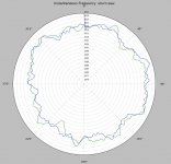
Here's the latest rev that "should" fix the text input issue. Much simpler labeling and set up of the radial axis. I went to a 7 pole butterworth filter at 60Hz on the data. There is no longer a rotation of the wiggles due to group delay if you filter at low frequencies
There is a small section at the top of the script where you can edit to do 45 (or any) RPM, filter the data at a different frequency, or change the Hz per radial div. If you want to do 1KHz just change to 1 Hz per div. Any sampling rate should work as long as you have 4sec of data, mono or stereo file.
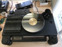
I finally got around to measuring my uturn (kickstarter) turntable as budget as you can get. For those who don't know this is as simple as it gets, an acrylic platter simple bearing with an o-ring belt and 12V motor. The belt is very weakly coupled to the platter. I had some mineral oil on my fingertips and touched the belt by accident and it stopped rotating after 10min or so.
There is a small section at the top of the script where you can edit to do 45 (or any) RPM, filter the data at a different frequency, or change the Hz per radial div. If you want to do 1KHz just change to 1 Hz per div. Any sampling rate should work as long as you have 4sec of data, mono or stereo file.
I finally got around to measuring my uturn (kickstarter) turntable as budget as you can get. For those who don't know this is as simple as it gets, an acrylic platter simple bearing with an o-ring belt and 12V motor. The belt is very weakly coupled to the platter. I had some mineral oil on my fingertips and touched the belt by accident and it stopped rotating after 10min or so.
Attachments
Last edited:
Works great on 3.6.2. I changed your maxf pad from .5 to 2 - just personal preference, I think the plot looks cleaner.
Great, I just added an edit that I missed to the above file (I hope it got there). I missed one instance of changing the Hz per tick. If necessary maybe Pano can change my attachment. BTW fractional frequency ticks work just fine and the text comes out correctly.
r1 = 20.-(maxf-if1)/3 #20 radial ticks at 3Hz is fixed, adaptive scaling
r2 = 20.-(maxf-if2)/3 #is an exercise for later
should read:
r1 = 20.-(maxf-if1)/Hz_per_tick #20 radial ticks at Hz_per_tick is fixed, adaptive scaling
r2 = 20.-(maxf-if2)/Hz_per_tick #is an exercise for later
Last edited:
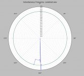
Here's a shot at a 3K carrier shifted to 2990 at 1/2 rev for a short time. It turns out you can't go from no signal to a pulse at 3K the transients in the transform are out of control.
This looks workable.
EDIT - The edit made it into post #562 so that is the current rev (rev3).
This looks workable.
EDIT - The edit made it into post #562 so that is the current rev (rev3).
Attachments
Last edited:
Still having some trouble with the glitch at 1K test frequency, if anyone has an issue here is one line to add. As I try more files if I can't get the built-in filter initialization to work 100% I will just add this permanently. It does not seem to be a problem at 3k or 3.15K. Just add the line in red. The other option was what I did the first time which creates a fixed rotational offset between LD's way and this way (at the time I wanted to get everything to match). Since the start of the data is arbitrary padding the beginning and rotating back to zero would be best within the context of only doing it this way, i.e. If you grab starting at 10s you get starting at, for instance, 10.1s while LD would get starting at 10s. Using the reference pulse would fix this automatically.
I don't know how many folks have noticed but projecting this way actually creates a cone surface receding away from the viewer at the center. You can see this with a large FM test file. It the modulation is a sine wave it is distorted, sort of folded in toward the center. The reason I mentioned this is that a seriously off center LP does not give a nice off center circle but an ellipse.
if1 = freq1[0:int(Fs*sec_per_rev)]
if2 = freq1[int(Fs*sec_per_rev):int(2*Fs*sec_per_rev)]
if1[0:2000] = if2[0:2000]
I don't know how many folks have noticed but projecting this way actually creates a cone surface receding away from the viewer at the center. You can see this with a large FM test file. It the modulation is a sine wave it is distorted, sort of folded in toward the center. The reason I mentioned this is that a seriously off center LP does not give a nice off center circle but an ellipse.
Last edited:
I shouldn't worry about it, and certainly it's not worth this level of complexity and imposition to address.If you grab starting at 10s you get starting at, for instance, 10.1s while LD would get starting at 10s. Using the reference pulse would fix this automatically.
I thought that, for the purpose of JP's experiment, we would just use a visual cue in the .wav file, such as a pulse on a 2nd channel, to select a start point, and that would serve.......?
Not just 'seriously' off centre, the tolerance of hole position and hole/spindle dimensions has to be quite tight to avoid the issue. In practice, many normal LPs have significant off centre or loose fitting holes, and this is by far the largest cause of audible pitch variation in normal playback, IME. Even for some test records.The reason I mentioned this is that a seriously off center LP does not give a nice off center circle but an ellipse.
LD
Even for some test records.
This is Analogue Productions 'The Ultimate Analogue Test LP'. I've several of their pressings. For all they do right at QRP, they couldn't center a spindle hole to save their lives.
Attachments
The centring error in that plot might be ~ +/- 200um.........This is Analogue Productions 'The Ultimate Analogue Test LP'. I've several of their pressings. For all they do right at QRP, they couldn't center a spindle hole to save their lives.
Not only does hole location need to be precise, any slop in the fit on a spindle might well be enough to do it..........
......and spindles vary in diameter from TT to TT, as do hole diameters........
It's yet another elephant in the room (!)
LD
I thought that, for the purpose of JP's experiment, we would just use a visual cue in the .wav file, such as a pulse on a 2nd channel, to select a start point, and that would serve.......?
LD
I'm over thinking this, yes the position cal eliminates the problem totally and without it it does not really matter. Easy permanent fix but I will wait for any other inputs for a while.
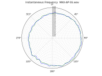
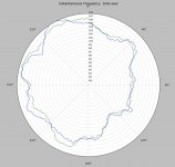
How's this for off center or what??? (RCA STR170). Yes, even I can hear it.

Attachments
Last edited:
That does look very bad, Scott - but remember scale. The frequency varies by +0.8% to -0.2% of nominal at the extremes.
But the trace varies 50% of the graph distance, leading the eye to think the variation is huge. If the graph scaled spatially the same as the frequency variation everything would fit easily between two lines.
The LP isn't anywhere near as far off center as the trace is.
But the trace varies 50% of the graph distance, leading the eye to think the variation is huge. If the graph scaled spatially the same as the frequency variation everything would fit easily between two lines.
The LP isn't anywhere near as far off center as the trace is.
The LP isn't' anywhere near as far off center as the trace is.
That was the effect I wanted folks to be aware of. A second projection (resulting in variable radial tick spacings) would mitigate this but I'm not up for that now.
As discussed on this thread, audibility perception of 0.55Hz pitch variation (eccentricity), ie nuisance factor, is commonly accepted to be significantly below that of the 4-16Hz FM range, ie vibrato.
IIRC a typical threshold for detection of pitch warble in the most sensitive range is about +/- 0.05%@3kHz. One can verify for oneself, by listening to the calibration tones already posted in this thread. Personally I can hear vibrato at +/- 0.1%@3kHz, so long as my head is still. I guess there's some internal brain compensation for movement, because the magnitude of pitch shift detectable is lower than Doppler shift from certain head movements, IIRC !
lD
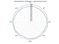
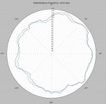
This type of tool is beginning to be fun and useful now. I noticed my belt develops a "kink" when left standing in one position for a long time so I repeated my test with a new LP (Telarc Omni Disk) and an hour of "burn in" rotation.
The frequency is much better making me sceptical of the absolute cal on the much older CBS disks and I noticed the pulley has a slight burr that makes a tiny ticking sound. By casual checking it seems to be the source of the regular wave. If I could eliminate that this is not bad for a $200 belt drive table.
EDIT - One flaw on this table is that they undersized the post very slightly from the RIAA absolute min spec (there is one) so perfect centering is essentially impossible.
Attachments
Last edited:
- Status
- This old topic is closed. If you want to reopen this topic, contact a moderator using the "Report Post" button.
- Home
- Source & Line
- Analogue Source
- Turntable speed stabilty