Using a Arduino Tach I managed to get 33.33/33.34 with ~33.10hz (33rpm), not very stable tho.
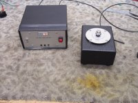
Here's a picture using the motor with a TT Project 1xperience.
Dropbox - IMG_4901.JPG
That motor is pretty! FWIW, tension, grip, and alignment of belt does seem to effect the tachometer measurements for speed bobble. Since you don't seem to have grooves on your platter, maybe there isn't much you can do about belt travel. On my VPI platter and motor pulley, I get more severe bobble if the belt isn't exactly perpendicular to the plinth between platter and pulley. Is there any travel in your pulley groove? Can you add a tensioner between pulley and platter? But if it's just bouncing between 33.33 and 33.34, that's not bad at all, IMO.
My VPI Classic turntable is fully controlled with SG4 controller and monitored with Arduino tachometer. Every occasion it'll show some drift .001-.005 rpm either way. I think its impossible to have a full "quartz lock" like some Technics SL1200. It also takes some time to stabilize due to room temperature and speed vary possibly to other mechanical factors from my own machined pulley quality, the belt I have and use, the tt mechanical integrity and other factors causing a tiny degree of drift. Ultimately I accept for what its can do and doesn't affect the music I listen to. Its all alright to me so far.
Absolutely, and soundwise you can't tell the difference, which I guess is the most important thing after all. It's just one of those achievements that you want to pursuit but it depends on several factors which make almost impossible to make it happen, especially with belt drive. That is why I want to build a TT to try to get a "silent and stable machine" which imply a better sound. Sure is fun but can be a real headache! Thankfully, the motor section is almost finished. Thanks all!
Mattzan,
The SG4 speed controller is now a key component and the most significant addition to my turntable system. I cannot do without it now. Due credit and a lot of appreciation to Bill who shared the design with whoever is able to build it to benefit from it all.
My project is still without a proper chassis but working very nicely (I constantly have wild ideas of perfecting it just for fun), which I will implement all in good time.
Thanks again Bill.. kowtow to you.
Greetings,
I have completed building this controller. I am using a BLWS motor from Anaheim Automation. The motor runs but I am not sure it's as smooth as it should be. My unscientific approach is to hold it in my hand while running. It's fairly smooth but I can feel some small vibration. Perhaps that is normal. I believe I followed the instructions correctly to balance the output. I get only about .02 volts at the test point. When I use the reduced voltage mode on the SG4 to adjust voltage down to the 3.8 Vrms at the 0 degree output, I get a slightly different voltage at the 120 and 240 degree outputs. Is this normal? Should I do more balancing with the trimmers on the MA-3D board? Perhaps it is running as smoothly as it should.
A couple other questions: I have not yet mounted this motor to use with my VPI table. I purchased a standard pulley from the source mentioned in this thread. If I require a different rotational speed from the motor in order to make it work with this pulley and platter combination, do I adjust the frequency using the SG4? Is any balancing needed after that?
Finally, I'm curious about the extra wires that are coming from my motor. I used the Red, Black, and Yellow that came out the same grommet and didn't touch the other wires.
My apologies if these questions have already been answered. I have read through this thread and can't find the answer.
Thanks for the assistance.
Bill
Last edited:
The vibration if you hold it in your hand is normal; it needs some mass loading. If you hold it tight against the bench, it should run without vibration. Mounting it in a metal enclosure will do the same.
Adjust the frequency with the SG4; you should not have to rebalance the outputs once set.
I remove the hall sensor assembly and all the extra wires. Take the motor housing apart via the 3 screws from the top. Make sure not to loose the washers that load the bearings in the top and bottom housing. The hall assembly is held in with 2 screws.
The vibration if you hold it in your hand is normal; it needs some mass loading. If you hold it tight against the bench, it should run without vibration. Mounting it in a metal enclosure will do the same.
Adjust the frequency with the SG4; you should not have to rebalance the outputs once set.
I remove the hall sensor assembly and all the extra wires. Take the motor housing apart via the 3 screws from the top. Make sure not to loose the washers that load the bearings in the top and bottom housing. The hall assembly is held in with 2 screws.
Thank you very much for the fast reply and thorough information.
And a big THANK YOU for another fine project! I'm anxious to get this hooked up to my table -I'm sure it will be an improvement over the stock VPI motor!
The vibration if you hold it in your hand is normal; it needs some mass loading. If you hold it tight against the bench, it should run without vibration. Mounting it in a metal enclosure will do the same.
Adjust the frequency with the SG4; you should not have to rebalance the outputs once set.
I remove the hall sensor assembly and all the extra wires. Take the motor housing apart via the 3 screws from the top. Make sure not to loose the washers that load the bearings in the top and bottom housing. The hall assembly is held in with 2 screws.
The motor is amazingly smooth when just sitting on the bench! Can't wait to get it installed tomorrow. Also it's good to have those extra wires out of the way.
I have the BLDC motor running and driving my VPI table. I'm very pleased. thanks for all your assistance and for this nice design. Here's a couple photos of current incarnation. Nest iteration will put SG4 and MA-3D boards into same enclosure with the motor.
Attachments
I connected my new motor to the VPI table today. It worked perfectly for about an hour. Very smooth and completely silent!
After about and hour or so, it began to slow down substantially. then it would jump back to proper speed and play correctly for a bit, but then repeated the slowing process. I was able to watch this using my KAB strobe, so I'm sure it's not my hearing.
I noticed that the motor was difficult to turn when the SG4 was in standby. Is this normal? What should I do to correct the speed problem?
I don't really understand BLDC motors operating in this mode well enough to diagnose, although I suspect it something in the controller that might need adjustment. Is this motor just acting like a 3 phase AC motor.
Thanks so much for any assistance.
Bill
The motor is driven as a 3 phase AC synch motor so it should hold speed as long as the SG4 is putting out the correct frequency.
The motor will be difficult to turn by hand in standby as long as power is applied to the amp. Unplug power from the MA3D to check the motor (turning it by hand).
Did you set the reduced voltage lower for the running voltage? The motor will reach ~120°F at ~10W which should be no problem. If the motor is getting extremely warm, you may need to reduce the running voltage. If the motor slips out of synch or stalls, the voltage is too low.
Thank you. I can easily verify the output frequency of the SG4 using a 'scope.
I did set the reduced voltage according to the instructions in the build document. It's possible that I didn't do it correctly so I will go through the process again.
The motor did become slightly warm but only a bit above room temperature and I'd say less than 120 F. Sounds like I might need to increase the voltage slightly?
Thanks for the information about how the motor functions. I generally understand how a 3 phase motor works, based on readings and information here on DIYAudio - I have a Pabst motor on my Empire tables for which I am building an SG4 controller.
Thank you!
I have just gone through the setup process again, from the beginning. I was able to get output voltage balanced at TP1 to about .015 v. I notice that the voltage for 33/rpm is 3.4 Vrms at 0 degrees and 3.3 Vrms at 120 and 240. Is this a problem? I could adjust to get these the same, I think. Have yet to re-test after re-setting the adjustment.
If they are summing to zero at TP1, they should be the same level at all 3 outputs, but it's not super critical. Check that the phase is set to 120 and 240 for each output (SG4 set up).
Using 8 bit math for the phase accumulators, the phase will not be exactly 120/240, but 119.53125 and 240.46875 deg.
Using 8 bit math for the phase accumulators, the phase will not be exactly 120/240, but 119.53125 and 240.46875 deg.
SG4 and MA-3D boards+ IC required (please!)
Hi gents, hope all builds are going well,
Decided to rebuild my working implementation of these devices (due to my cr*p soldering!)
So has anyone got : 2 x SG4 and 1 XMA-3D boards
and 2 x IC/microprossor chip with the latest firmware please.
I can pay vial PayPal, so if anyone wants to play please PM me, thank you all for your help andbig up for a Mr Pyramid and Ralph easpecally - very kind hearted gents.
Best regards to all
Johnny
2 x SG4 and 1 x MA3D PCB for turntable required
Hi again, still up for 2 x SG4 and 1 x MA-3D PCB, any Osh park PCB orphans out there?
(Thanks to Ralph for helping out with the Chip.)
can do via Pay Pal
Please PM me and we can "do the necessary"
Best regards
Johnny
Hi again, still up for 2 x SG4 and 1 x MA-3D PCB, any Osh park PCB orphans out there?
(Thanks to Ralph for helping out with the Chip.)
can do via Pay Pal
Please PM me and we can "do the necessary"
Best regards
Johnny
Last edited:
- Home
- Source & Line
- Analogue Source
- 3 Phase Class D amp for DIY BLDC motor Drive