The angle of the grooves shouldn't make any difference in speed, except for how they affect the depth.
You said you followed the same diameter as the previous (VPI factory) pulley? Did the pulley have both 33 and 45 RPM spindles, or was it only 33? If it was 33/45, the spindles are tapered for coarse speed adjustment so the diameter at the top will be undersized and the diameter at the bottom of the 33 spindle will be oversized. If you measured at the top, that would account for your slower speed.
Hi Bill,
Its the original VPI 33/45 stepped pulley that I modeled the new only for only 33rpm with multiple belts if needed.
I agree the diameter would affect the resultant speed. OTH, I read somewhere claiming a different groove angle on a consistent pulley diameter would change the speed incrementally pointing how the stepped VPI pulley works. I don't know if this is true.
Yes, I used the same measurement on the top and replicated that on the new pulley. I didn't realise the possibility of an incremental measurement further down each step. This being a first, I didn't realise the importance of "tapered pulley" but believed it was a different groove angle on each step that gave user option to vary accordingly.
Guess its back to the drawing board and I measure again the 2nd or 3rd step diameter and analyze where I've missed or gone wrong. Lastly I'm retaining the use of the original VPI belt which is about 2mm thickness.
A 2nd test with a loaned speed controller revealed increasing to another 0.33hz to get it correct.
Thank you for your prompt response,
Lee
Update:
Further to investigating of causes why its off the mark
1) I brought out to use a more accurate Micrometer screw caliper (which I failed to use) and measured each step on the original pulley. It measures 0.754", 0.755" and 0.756". The new pulley measures 0.7535 thereabout. I had used the top diameter and measured with an ordinary digital Vernier caliper. My Mm caliper revealed more exacting measurements during the comparison. I see the problem now.
2) I stuck a piece of 3M transparent tape around the new pulley to see a possible effect of change, increasing the diameter by 0.004", fitted the pulley and measured the platter RPM, now it checks out at 33.4rpm which is closer to ideal.
3)I reckon its back to the machine shop to have one made at 0.7555" diameter and maintain everything else.
4)This is scary! Am tackling very close tolerances to obtain the right speed. I hope the machine shop can turn one out to my expectation.
I was able to finally get the motors (BLWR) after a lot of going back and forth with AA - ultimately had to have a friend get them from AA and ship them over - I take it AA have a lot of large orders and are not that willing to accommodate individual purchasers that their online system will not accommodate.
@Pyramid, your efforts are much appreciated - both in offering this project and communicating with AA.
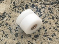
That said, back to the business of motors and pulleys - attached here is one of the failed attempts at a pulley (*). It is made of Delrin with a bronze hub, and, even though we have tried numerous times, cannot machine a satisfactory ID of 4mm with the bronze hub - using both (1) multiple precision reamers and (2) grinding rods.
(*) The photo is crap, but it was the best I could do with limited camera options, and the pulley being white.
Thought the issue might be with the motor shaft, but both motors, measured with a precision Mitutoyo micrometer, are well within the spec published by AA.
As a last ditch effort, we machined a pulley from Delrin without the bronze hub, same procedure as tools as earlier, and achieved an interference fit. Further testing at a range of 200 - 2800 rpm revealed a runout of ~0.005mm.
This pulley is a bit different that the ones presented here due to the design of my turntable and experimentation with a minuscule flywheel effect. The diameter of the belt area (working pulley diameter) is 16mm, for a 1:20 drive with my 320mm platter.
After all this, I can understand how machine shops have difficulties providing satisfactory results over a larger run of pulleys without dry fitting against each motor. The SDP-SI pulleys might be a very good option for both BLWR and BLWS motors - but I have been unwilling to pay the shipping premium to test that hypothesis.
On to building the electronics now - so another question to @Pyramid - I have asked earlier about the possibility of stacking the boards for a compact enclosure - apparently that is doable.
However, I failed to note the height of the C21 capacitor on the MA-3D board. @rsritchey had asked earlier about an alternate capacitor due to similar reasons here:
http://www.diyaudio.com/forums/anal...s-amp-diy-bldc-motor-drive-8.html#post5118411
My specific question is two-part:
1. Is there a replacement you would suggest here that would come out at a lower height (not more than say 15mm?)
2. Alternatively, can one mount C21 off-board at an angle (with longer leads, of course) - could that cause circuit stability issues?
Option #2 is preferable unless it compromises functionality.
Again, much appreciated for an excellent gift to the DIY community.
@Pyramid, your efforts are much appreciated - both in offering this project and communicating with AA.
That said, back to the business of motors and pulleys - attached here is one of the failed attempts at a pulley (*). It is made of Delrin with a bronze hub, and, even though we have tried numerous times, cannot machine a satisfactory ID of 4mm with the bronze hub - using both (1) multiple precision reamers and (2) grinding rods.
(*) The photo is crap, but it was the best I could do with limited camera options, and the pulley being white.
Thought the issue might be with the motor shaft, but both motors, measured with a precision Mitutoyo micrometer, are well within the spec published by AA.
As a last ditch effort, we machined a pulley from Delrin without the bronze hub, same procedure as tools as earlier, and achieved an interference fit. Further testing at a range of 200 - 2800 rpm revealed a runout of ~0.005mm.
This pulley is a bit different that the ones presented here due to the design of my turntable and experimentation with a minuscule flywheel effect. The diameter of the belt area (working pulley diameter) is 16mm, for a 1:20 drive with my 320mm platter.
After all this, I can understand how machine shops have difficulties providing satisfactory results over a larger run of pulleys without dry fitting against each motor. The SDP-SI pulleys might be a very good option for both BLWR and BLWS motors - but I have been unwilling to pay the shipping premium to test that hypothesis.
On to building the electronics now - so another question to @Pyramid - I have asked earlier about the possibility of stacking the boards for a compact enclosure - apparently that is doable.
However, I failed to note the height of the C21 capacitor on the MA-3D board. @rsritchey had asked earlier about an alternate capacitor due to similar reasons here:
http://www.diyaudio.com/forums/anal...s-amp-diy-bldc-motor-drive-8.html#post5118411
My specific question is two-part:
1. Is there a replacement you would suggest here that would come out at a lower height (not more than say 15mm?)
2. Alternatively, can one mount C21 off-board at an angle (with longer leads, of course) - could that cause circuit stability issues?
Option #2 is preferable unless it compromises functionality.
Again, much appreciated for an excellent gift to the DIY community.
Attachments
My specific question is two-part:
1. Is there a replacement you would suggest here that would come out at a lower height (not more than say 15mm?)
2. Alternatively, can one mount C21 off-board at an angle (with longer leads, of course) - could that cause circuit stability issues?
Option #2 is preferable unless it compromises functionality.
Option #2 will work. C21 is a reservoir cap; there are 0.1uFd caps on each supply pin of the amplifier chips for stability. You can mount the cap on the back side of the board (observing the proper polarity arrangement) and bend the leads at right angles to mount the part flat.
You could also try a short cap with the same lead spacing mounted on the top side of the PCB. You can reduce the value somewhat (use the same voltage rating though), but I would keep the value as high as possible and definitely don't go below 100uFd.
That said, back to the business of motors and pulleys...
...After all this, I can understand how machine shops have difficulties providing satisfactory results over a larger run of pulleys without dry fitting against each motor. The SDP-SI pulleys might be a very good option for both BLWR and BLWS motors - but I have been unwilling to pay the shipping premium to test that hypothesis.
I'm not sure why one would need a brass insert in this application. The torque needed to start and drive a turntable platter isn't high enough to necessitate a grub-screw fixing. I found, personally, that with both tight-grained wood like maple, or Delrin/Acetal an interference fit is more than adequate (one needs only to drill a hole the exact size of the shaft, and the fit is perfect.) And machining for an interference fit is much easier; allowing me to get a passable pulley with only a drill press, table saw, and the motor itself as a lathe to do the final shaping and polishing.
That said, the SDP-SI pulleys with brass or aluminum inserts are quite nice and run true (I ordered a couple). But, unfortunately, their flat-belt pulleys don't have upper or lower belt guides, so the belt just falls right off. If using a round O-ring style belt, their pulleys are great--and a bargain.
I have really been enjoying my set-up with the BLWS motor, and homemade pulley. Pyramid's controller is a real treat!
Option #2 will work. C21 is a reservoir cap; there are 0.1uFd caps on each supply pin of the amplifier chips for stability. You can mount the cap on the back side of the board (observing the proper polarity arrangement) and bend the leads at right angles to mount the part flat.
Much appreciated!
I'm not sure why one would need a brass insert in this application.
Based on the SDP-SI pulleys, I thought it would be a good idea.
") It might have been one, of course - but we haven't yet managed to make it work.
It might have been one, of course - but we haven't yet managed to make it work.And as you stated - for this application is probably not needed.
Has anyone else had issues with electrical noise coming from the MA-3D / SG-4 combination? I'm getting a hum that only starts when the MA-3D is plugged in, and gets worse when the motor is actually started.
I don't have an enclosure for the motor control boards (or the motor), nor is any of it grounded. There is good physical separation- all the motor bits sit on one side of the platter, and the tonearm, preamp, and amp on the other. Each side is plugged into different outlets (though not different circuits).
The tonearm is probably quite susceptible to acting like an antenna- it's based on the Altmann design, with no shielding.
Do I need to do something to ground the motor side components? Or would an enclosure for the motor control boards be a better place to start? Or is my time better spent looking at the tonearm wiring first?
The tonearm is probably quite susceptible to acting like an antenna- it's based on the Altmann design, with no shielding.
Hello,
You must shield to ground any exposed tonearm wires which run along the tonearm wand to the RCA. These wires are sensitive enough even if its through a non metallic wand to pickup external interference or EMI noise. Twist each pair separately and shield them all as much as possible.
Lee
Balancing outputs
Hi Bill
Sorry if this question has been asked before, this thread and the others related to it have gotten quite long. I have tried to keep up on things.
I've got my project together and successfully powered up and responding. I'm having difficulty understanding part of the calibration process that is to be done before I connect to my BLWS motor.
I am using an AC voltmeter and have successfully adjusted the output of all three amp channels to 4.2 VRMS by using the pots. However, I am confused by the next set of instructions:
"To balance the outputs, move the scope or the AC voltmeter to TP1 and carefully adjust all 3 pots for MINIMUM output at TP1. When the levels are the same, the 3 signals should sum to zero (or a very low reading)."
I was adjusting the output channels by clamping the negative probe to ground on the MA3D board and probing with the positive at the output header (see below).
I tried probing to the TP1 contact with the positive probe with the negative probe still clamped to ground on the board. The meter just started giving me crazy fluctuations with O.L.
I then tried moving the probes to take AC readings between the outputs and TP1. In this scenario I get readings very close to the 4.2VRMS I was initially adjusting the pots for, with perhaps a difference of .01 V in either direction from one channel to the next.
Am I performing the correct test in order to complete the balancing procedure?
I'm not sure what you mean by having them all at "minimum output" and also "sum to zero", unless you mean they should all be as closely adjusted to the 4.2 VRMS figure as possible by testing between the amp outputs and TP1?
Thanks for any help you can provide.
Attachments
It's quite straightforward, if you sum 3 phases that are exactly the same amplitude, and exactly 120 degrees apart the resultant signal will be 0. What you're attempting is to set the outputs to the same level, before adjusting the phases for minimum vibration TP1 is the summing point of the 3 phases.
If the DVM is bouncing around and showing overload, it is probably auto-ranging and switching between 2 ranges. If you can, manually select a range of 1VAC or less, then measure between TP1 and ground. Do not make large adjustments to the pots once they have been set for 4.2VAC at each output; what you are trying to do is very finely trim each output so they are exactly equal. As Ralph said, 3 signals of the same amplitude 120° apart will sum to zero. In practice, you will never get zero VAC at TP1, but by careful adjustment, you should be able to get a minimum reading ~30-50mVAC.
I'm out of my depth when it comes to electrical work, so I apologize in advance if this is a dumb question, but would any of Anaheim's own BLDC motor controllers (Anaheim Automation | Low-Cost Brushless DC Drivers/Controllers, more specifically MDC200 - Brushless DC Speed Controllers) work effectively with the BLWS231S-24V-2000 to serve as adjustable turntable motor control, or is there something else that Pyramid's SG4 controller and 3 Phase Amp do that none of Anaheim's controllers can (ie: smoother motor control, etc.)? Some of them appear to have built-in hall sensor input for motor control, and others seem to even have built-in dials for manual speed control. If their controllers do the same/similar job as Pyramid's controller and/or amp, could it be used by those of us without soldering skill but with programming skill and an Arduino tach to become a self-adjusting speed control system?
Again, if I'm way off the mark, I apologize.
Again, if I'm way off the mark, I apologize.
Last edited:
All of their controllers treat the motor as a DC motor, where they change the drive voltage to change the speed and use the hall sensors as feedback to compensate (or measure) the speed. The SG4 operates the motor as an AC synch motor where the speed is set by the frequency and the voltage is compensated accordingly. The two methods are almost opposite in approach.
The AA controllers will have poor speed resolution and stability and the motors will exhibit cogging.
The AA controllers will have poor speed resolution and stability and the motors will exhibit cogging.
I´m starting to make the arrangements to upgrade into the BLWS231S + MA3D combo and I believe the main problem for me would be anything that would involve custom precision machined parts, as this service here in Brazil is extremely expensive unless in large amounts.
With this in mind, I´m trying to find some off the shelf solution for the pulley and I had this idea:
Use a 1/4" to 3/16" shaft coupler (Set Screw Shaft Couplers) and a 1" 3/16" shaft (3/16" Stainless Steel Precision Shafting) thus creating a 1/4" - 3/16" shaft reducer so I could just use the VPI stock pulley (actually, I intend to use the HRX one). This would raise the motor´s final height up to an inch, so I´d need to compensate this by elevating the turntable (easy to do).
The HRX pulley has a fixed diameter, but I could not find online it´s actual measurements only that it would make the platter spin at 45 RPM if used without the SDS controller.
So... would this work?
Im going to post this here as well incase someone has any insight and isn't subscribed to the other thread related to the BLDC motors.
"I have been happily using this motor and pyramids controller for a while now. I have a slight issue that doesn't seem to affect performance in any audible way but bothers me to no end. My motor is slightly noisy. As soon as I turn the motor on I get some small noise that sounds like something is rubbing. I thought it might be the wave washer that held the shaft in place or the bearings, but I am not totally sure."
Just curious if anyone else has had this issue and/or found a way to alleviate it.
Like I mentioned in the other thread, I have experienced a scraping noise coming from the motor. This motor has been disassembled so many times in testing, I may not have pressed the pulley or bearings on correctly. I just put some of these bearings in being careful to have the spindle support pressing on the bearings & pulley. So far it's very quiet.
XiKe 10 Pack 625-2RS Precision Bearings 5x16x5mm, Rotate Quiet High Speed and Durable, Double Seal and Pre-Lubricated, Deep Groove Ball Bearings.: Amazon.com: Industrial & Scientific
Hard to tell if it's also your bearings. Mine were quite smooth by turning them by hand as well.
Cheers,
Gregory
XiKe 10 Pack 625-2RS Precision Bearings 5x16x5mm, Rotate Quiet High Speed and Durable, Double Seal and Pre-Lubricated, Deep Groove Ball Bearings.: Amazon.com: Industrial & Scientific
Hard to tell if it's also your bearings. Mine were quite smooth by turning them by hand as well.
Cheers,
Gregory
- Home
- Source & Line
- Analogue Source
- 3 Phase Class D amp for DIY BLDC motor Drive