Shouldn't be a problem. I'd put the SG4 on top so you can get to the buttons for calibration modes.
Much appreciated.
I always liked the solution used in the Artemis SA1 turntable. They used a flat belt and a tensioner to keep constant force on the belt. The attached picture is taken from an article about the SA1 in Positive Feedback magazine. artemis labs sa1
Anyone have good leads on where to buy hardware to make a diy tensioner?
Thanks,
---Gary
If you have any machining capabilities (even a dremel and a lot of time) I would think you could put together a roughly functional belt tensioner quite easily with bits from McMaster Carr (or if you have a good hardware store near you with all those drawers and bins of fasteners, spacers, springs, etc.) All you would need is a short swing-arm (aluminum or hardwood, even) mounted on a bronze bushing for the pivot. You would also need a spring mounted between the swing-arm and turntable plinth to provide tension. Some silicone oil or grease in the pivot would damp the springiness. It might take some experimenting with different viscosities to get it right.
The spindle (capstan? a capstan is powered, right?) would just be two small cartridge bearings stacked and some spacers below them to achieve the correct height. It does not need to be fancy or even that precise to work properly.
With a little messing around, and some trial and error, I'm sure you could come up with a highly functional tensioner. One of the biggest challenges might just be cutting the arched slot in the top plinth for the tensioner spindle to stick out of.
Doesn't the Artemis use Magnetic tape for a drive-belt? No flex or stretch, I suppose, and VERY thin, but wouldn't the mylar tend to transmit motor vibartion? It is not as internally damped as neoprene, rubber, polyurethane, or whatever.
I’m working on the BLWS now, (it is quieter as Pyramid stated).
Cheers,
Gregory
Wait, I must have misread an earlier post. The BLWS is quieter than the BLWR? For some reason I thought the BLWR with more poles (8 vs 4) would have been the smoother spinner. Was I wrong?
Strangely, I have both of these. I picked them out a couple of years ago independent of this thread. Should I use BLWS instead?
I know, I know. The correct answer it to try both and see which I prefer in my application.
Gregory- when you get the BLWS up and running, I am quite interested in what you think about the difference between the two.
Best,
John
Last edited:
Hi John,Wait, I must have misread an earlier post. The BLWS is quieter than the BLWR? For some reason I thought the BLWR with more poles (8 vs 4) would have been the smoother spinner. Was I wrong?
Strangely, I have both of these. I picked them out a couple of years ago independent of this thread. Should I use BLWS instead?
I know, I know. The correct answer it to try both and see which I prefer in my application.
Gregory- when you get the BLWS up and running, I am quite interested in what you think about the difference between the two.
Best,
John
I had the BLWR up & running for quite a while before finally getting the BLWS, Lots of testing different pulleys and reassembly. The noise was mostly from the bottom bearing and I replaced both with these last Friday.Amazon.com: 5x16x5mm Hybrid Ceramic Brushless Motor Ball Bearings (2): Industrial & Scientific The motor is much quieter now and we'll see if that lasts.
I had made the pod on an eccentric for adjustable belt tension but will make a new one centered since I'm now running stock size pulley.
I've started work on the pod for the BLWS, a bit smaller than what Pyramid designed as I have to work within the existing dimensions of the Oracle. Will report back on findings.
Cheers,
Gregory
First of all, thank you Pyramid for putting this project together! It is just what I have been wanting to find for a few years now.
I just got my SG4/MA-3D and BLWR up and running. Super easy project! Huge thanks to Pyramid for putting together such a thorough assembly manual, and even a Mouser project-cart. All this was extra work on Pyramid's part, but made the project fool-proof.
And thanks to Twystd for the programmed uPs!
The motor spins now, with no detectable cogging. When I had the motor on the original Annaheim Automation controller the cogging (and motor whine) were pretty bad.
I think I still need to play around a bit with the individual phases, and phase voltages. The motor is vibrating a little more than I had hoped, BUT! when installed in my table it is MUCH quieter than the Papst (with no controller, just faking cap)-- both in audible noise directly form the motor itself, and in rumble transmitted through the cartridge. My table is VERY quiet now, but I think I can get it better.
Also, the wood pulley I made using the motor itself as a lathe works very well, and runs nice and true. It is very easy to do (hint, hint).
I noticed that when measuring TP1 I could get 0.00VAC on my DMM if I had RV1 adjusted slightly higher than RV2, RV3. Maybe I will adjust the pots back so that they all read equal values before I start to mess around with the SG4 phase adjustments.
Has anyone tried tweeking the individual phases on the SG4 yet? Any success?
Best,
John
Last edited:
Pyramid- I forgot to mention. I did some listening last night, and aside from the lowered noise-floor (and more important to me), with the SG4/MA-3D, the timing on my vinyl is infectiously rock-solid. It was hard not to bob my head or tap my toe, no matter what I put on! (if you imagine me air-drumming for two hours straight, you wouldn't be off the mark.)
Again, a huge thanks!
Best,
John
Again, a huge thanks!
Best,
John
Last edited:
Hi all,
I'm just wondering if anyone has a spare board for the MA-3D, if you have the SG4 one as well + programmed chip it could work out well also? I'm based in the UK but I could possibly have one delivered to family in Canada and get stuff that way.
Just another Q, apologies if it has been asked before - is it possible to share power supplies for the MA-3D and the SG4 ?
Thanks again to Bill for his kind work!
Julian
- is it possible to share power supplies for the MA-3D and the SG4 ?
Yes, the MA-3D has a 12V regulator to supply the SG4 with power. The MA-2D should be powered from a 15VDC wall adapter.
It is a 2.1mm x 5.5mm cable that I had lying around. Mouser sells them (cables) but they are more expensive than the wall adapter it came from. They sell the individual plugs for <$2. You can also find both connectors and cables on e-Bay.
Enter: 2.1mm DC cable or 2.1mm DC connector in either search case.
Enter: 2.1mm DC cable or 2.1mm DC connector in either search case.
Is the SG4 set to maximum (128) in the reduced voltage mode?
Are you supplying 15VDC to the MA-3D?
Yes 128.
Yes, 15.64V.
Attachments
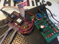
The caps on the SG4 LPFs appear to be different. Can you confirm the values?
The output of the SG4 at maximum should be ~1.75VRMS (5VPP). Can you confirm?
The MA-3D gain is fixed at 20dB (10x) so with the pots at maximum, the output should be pushed to the 15VDC rails. Does the output change with the adjustment of the pots at all? You should be able to reduce the output to zero and 15VPP (5.3VRMS). Are you measuring the output voltage at motor output pins?
The caps on the SG4 LPFs appear to be different. Can you confirm the values?
The output of the SG4 at maximum should be ~1.75VRMS (5VPP). Can you confirm?
The MA-3D gain is fixed at 20dB (10x) so with the pots at maximum, the output should be pushed to the 15VDC rails. Does the output change with the adjustment of the pots at all? You should be able to reduce the output to zero and 15VPP (5.3VRMS). Are you measuring the output voltage at motor output pins?
Thank you Pyramid for your attention. So, I got confused and I was measuring the input instead of the output. Never the less I could only get the 0 phase right (4.2VRMS), 120 and 240 keeps variating the voltage which makes impossible to be precise.
Here's a video: Dropbox - Video 08-11-2017 11 13 47.mov
TP1 I'm having 0.41Vrms. The output of the SG-4 is 1.75Vrms. The caps on the SG4 are all right (473, 104, 223, 10), I just used one different 223 film cap (yellow one). I used different 1uf elet caps on MA-3d that I had left here from different projects but I don't that's the problem.
As I was moving forward with the alignment I got confused on how to adjust the correct reduced voltage setting for 4.1VRms (BLWR) - where do I measure to get this right? The outputs of the SG4 on each phase I get max 1.75Vrms like I said before.
Thanks again for your help.
The variation isn't too bad; without a scope it is difficult to tell what might be happening. It may just be the connection at the PCB with either the positive or negative probe. Try to use alligator clips or some other method of sure contact. Also, check that the input to each phase is steady.Thank you Pyramid for your attention. So, I got confused and I was measuring the input instead of the output. Never the less I could only get the 0 phase right (4.2VRMS), 120 and 240 keeps variating the voltage which makes impossible to be precise.
Here's a video: Dropbox - Video 08-11-2017 11 13 47.mov
TP1 I'm having 0.41Vrms. The output of the SG-4 is 1.75Vrms. The caps on the SG4 are all right (473, 104, 223, 10), I just used one different 223 film cap (yellow one). I used different 1uf elet caps on MA-3d that I had left here from different projects but I don't that's the problem.
As I was moving forward with the alignment I got confused on how to adjust the correct reduced voltage setting for 4.1VRms (BLWR) - where do I measure to get this right? The outputs of the SG4 on each phase I get max 1.75Vrms like I said before.
TP1 will probably never get to zero, but you should be able to get it down to 20 or 30 mV. If the output levels are not the same, then TP1 will be higher; if the levels are exactly the same and there is no distortion, the TP1 will be very close to zero.
Adjust the reduced voltage setting for 4.1VRMS at the outputs.
Yes the input is steady, so I can rule out the sg-4 right? I managed to get 0.37 tp1 and decided to go foward with the alignment. Installed the motor but it didnt function smoothly, lots of vibration, kind of chocking sometimes very weird.
I think Im gonna start fresh, dont know what happened.
Thanks again Bill.
I think Im gonna start fresh, dont know what happened.
Thanks again Bill.
BLWR series: Machine a 4mm center bore pulley or use a 4mm-3/16" sleeve and use an existing pulley.
------snipped----------
If there is anyone with some machining capabilities, the attached file has CAD drawings for 600 RPM pulleys for both 4mm and 1/4" center bores.
Hi Bill,
Very recently I had a custom metal pulley machined out locally following your basic design but with alterations to diameter, height and more grooves to what I thought that suit my VPI Classic 1 Hurst motor at 500rpm/50hz. For main purpose and intent, I think I've achieved a good deal save for its a tad slower at 33.0rpm as opposed to original pulley at 33.33 - + 0.1rpm on the 2nd step. I followed the same pitch and groove angle as your design. I followed the same exact diameter as the previous pulley. My ears could discern music at 0.33rpm slower, but no matter if I ignore it all. My measurements are without the use of any speed controller and plugged into the wall socket which is quite consistent at 50hz most of the time.
I suspect its the groove angle of 120deg that could be the issue, perhaps a lesser degree say 60deg groove angle achieve making up for the discrepancy? I'm not sure. I've no way of telling whats the 3 angles of the original stepped pulley which does make a speed variation difference. I'm aware that there could be other calculations or fabrication limitations that obstruct ideal results. Can I kindly request your views on what I could do next to try achieve exactly as the original pulley?
Lee
Last edited:
The angle of the grooves shouldn't make any difference in speed, except for how they affect the depth.
The approximate formula for pulley diameter is:
(Pulley Dia + ½ belt thickness)/(Platter Dia + ½ belt thickness) = Platter Speed/Motor Speed.
If you can't change the motor speed (and you don't want to change the platter diameter), the only other variables are the Pulley diameter (including groove depth) and the belt thickness.
Unfortunately, your platter speed is slow, so the belt needs to be thicker or the pulley diameter needs to be larger. If the platter was fast, you could just machine the pulley slightly smaller.
You said you followed the same diameter as the previous (VPI factory) pulley? Did the pulley have both 33 and 45 RPM spindles, or was it only 33? If it was 33/45, the spindles are tapered for coarse speed adjustment so the diameter at the top will be undersized and the diameter at the bottom of the 33 spindle will be oversized. If you measured at the top, that would account for your slower speed.
Last edited:
- Home
- Source & Line
- Analogue Source
- 3 Phase Class D amp for DIY BLDC motor Drive