Nice! How's the speed stability, vibration and sound?
Sound is good and the speed seems stable. It's definitely quiet. Can you walk me through a way to measure wow and flutter? I have access to a pretty good USB A/D converter, from there I'm not sure where to go.
greyblob,
I'm very interested in the outcome. What material are you using? What file/drawing did you send them? Maybe it's time we start a new thread for just the pulley, so we don't keep hijacking this one.
The material is FDM printed ABS-M30, its suppose to be a high tolerance functional plastic that can be used in end product applications. I am going to send them the file that Pyramid put earlier in the thread after a quick check for measurements in cad. If this doesn't work or that pulley is off, I will probably design another one and or reach out to machine shops local to try and get one done.
Fremer uses the Dr. Fiekert app. It requires a test LP with a 3150 Hz test tone.
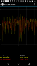
As it turns out, I was just given a test record with a 3150 test tone. I downloaded Dr Fiekert's app and gave it a shot. Attached is the result.
Attachments
looking for SG4 PCB (with V.1.3 Micro proc or grater)+ MA-D3 PCB populated/unpopulate
How do- gents, and thanks to Pyramid (of course)
Has any one got spare PCBS for the SG4+V1.03 chip and MA-3D PCB populated or un populated as my DC controller has just exploded
Also would be nice to get a Rotary encoder PCB (discrete components type) if possible?
I surmise there may be a pool of "extra" PCBS laying around?
Most thankfully yours
Johnny
3 Phase Class D amp for DIY BLDC motor Drive PCB Required
Hi again sorry to bother the forum,
My thanks to Ralph for sorting me out with the Chip and Sing Gen PCB.
Has any one got a 3 Phase Class D amp BLDC motor Drive PCB they want to sell (Populated or un populated)+Encoder PCB?
thank you sirs
Johnny
Hi again sorry to bother the forum,
My thanks to Ralph for sorting me out with the Chip and Sing Gen PCB.
Has any one got a 3 Phase Class D amp BLDC motor Drive PCB they want to sell (Populated or un populated)+Encoder PCB?
thank you sirs
Johnny
As it turns out, I was just given a test record with a 3150 test tone. I downloaded Dr Fiekert's app and gave it a shot. Attached is the result.
I was hoping someone would comment on this, as I have no idea if this is a good result or not. I did not know about Dr Fiekert's program before I took the motor housing apart, so I don't have a baseline measurement. Any opinions?
It looks like your speed accuracy is good (mean freq: 3150.7 Hz).
It's difficult to see the time scale along the bottom of the display. A lot of the instantaneous frequency deviation in a display is due to record eccentricity, warp and tone arm resonance. Eccentricity shows up as a waveform with a period of 1.8S (as does warp as it usually occurs once per rev). Tone are resonance is higher in frequency usually 8-12 Hz.
An eccentric pulley will show up as a 10Hz fluctuation at 600 RPM.
There should be a low pass filter setting in the software that reduces a lot of the higher frequency occurrences and gives you a better indication of the long term stability.
The controller and motor will not have much of an effect on the short term perturbations shown in the display. It will affect speed accuracy and long term stability.
Pully Diameter and Sine readings for 300 mm Platter@33.3RPM
Avast Gents,
Dear Sirs I have purchased a Bix platter from Diy HiFi Supply and its diameter is = 300 mm ( 11.811 Inches)
With respect to this Could any one tell me
a. What is the ideal pulley diameter for the motor?
b.What are the optimum sine wave readings for the
BLWR series motor for 33.3 RPM?.
Much Thanks
Johnny
This should get you close, assuming 600 RPM on the BLWR motor:
T= thickness of belt/2
pulley diameter=[(11.811+T)*33.33333/600]-T
If you use a 0.080" thick belt, the pulley diameter would be ~0.618" diameter.
The BLWR series motor needs 40Hz drive frequency for 600 RPM, but you will need to adjust it to get an exact speed of 33.333 RPM at the platter. Follow the alignment instructions for the MA-3D amp to set the output voltages for 33 and 45 RPM.
If you use the CAD drawings for the pulleys I provided (0.600" diameter), the frequency will be ~41.3Hz for 600 RPM.
Last edited:
All,
I got both boards built and my motor arrived today, builds went smooth and I didn't think I had any issues until I went to do alignment. My output readings are 15.5vrms and I reach the end of the potentiometer before I can even come close. Im not sure what my issue is and any trouble shooting would be helpful. I dont see anything odd but any checks I could do would be great.
I got both boards built and my motor arrived today, builds went smooth and I didn't think I had any issues until I went to do alignment. My output readings are 15.5vrms and I reach the end of the potentiometer before I can even come close. Im not sure what my issue is and any trouble shooting would be helpful. I dont see anything odd but any checks I could do would be great.
You have the MA-3D PCB? With a 15VDC supply there should be no way you are getting 15.5VRMS output as that would be ~44VPP. The pots on the MA-3D will allow you to adjust the output down to zero.
What is the AC voltage reading at the SG-4 output when set for 33.3?
What is the AC voltage reading at the 0° output of the MA-3D with the SG-4 in standby mode?
Can you post pics of the PCBs?
What is the AC voltage reading at the SG-4 output when set for 33.3?
What is the AC voltage reading at the 0° output of the MA-3D with the SG-4 in standby mode?
Can you post pics of the PCBs?
You have the MA-3D PCB? With a 15VDC supply there should be no way you are getting 15.5VRMS output as that would be ~44VPP. The pots on the MA-3D will allow you to adjust the output down to zero.
What is the AC voltage reading at the SG-4 output when set for 33.3?
What is the AC voltage reading at the 0° output of the MA-3D with the SG-4 in standby mode?
Can you post pics of the PCBs?
Yes I have the ma-3d PCB, and it may be my meter but I am getting ok readings with everything else so I am not sure.
the output for the sg-4 is 5VRMS to any of the output pins on 33.3. and with the sg-4 in standby it still reads a silly 15.4VRMS. the 120 reads the same and the 240 reads 6.3VRMS.
Here are pictures:
Phoenix DC controller - Album on Imgur
It looks as if your meter is reading peak-to-peak AC volts rather than RMS. The output of the SG-4 is 5VPP or 1.77VRMS.
The 0° and 120° outputs of the MA-3D come from U1, the 240° output comes from U2. With no input, the output of the chips should be a 15VPP square wave with a 50% duty cycle, when filtered by the inductors L2-L4 and caps C14-C16, should produce 7.5VDC and no AC voltage at the output connector.
If you are getting AC voltage out of the MA-3D with no input, the amps are probably oscillating. Look for a bad solder joint on U1, U2 or any of the components connected to them, or one of the tantalum caps may be in backwards.
Does your meter read frequency? If so, what is the AC frequency at the output connector of the MA-3D?
- Home
- Source & Line
- Analogue Source
- 3 Phase Class D amp for DIY BLDC motor Drive