Measured Response of EPC451C
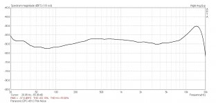
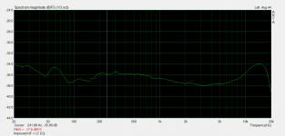
Here is the measured response of an EPC451C. Used the Ultimate Analogue Test LP, side 2, track 2, pink noise. Fed into the Panasonic CD-4 Demodulator, then into an ADC and measured using ARTA's spectrum analyzer (third octave smoothing).
Clearly, it has huge frequency response variations. My speakers are very linear and when I first played it, I immediately noticed that the response wasn't neutral. The 15 kHz peak is easily heard, as is the sub 50 Hz rise. I applied some filters as mentioned in my earlier post. This measurement just confirms my suspicions. The response swings more than 5 db from flat. For me, without correcting the response, this cartridge and demodulator system are unusable. With the correction, it is a very good system.
I'm curious to know how Kevin and others are handling these cartridge response deviations from flat. It would be great if others could post similar measurements because it would allow comparisons between different preamps, stylii, and even other strain gauge cartridges.
Note that in some cases, the cartridge response combined with the speaker response might produce an overall neutral response, resulting in a positive perception of the sound quality. In other cases, it might aggravate problems.
Attachments
The pre-amplifier discussed here actually has EQ to correct the grossest response errors below 50Hz and above roughly 7kHz. I don't currently do anything in the midband.
The very simple EQ currently implemented is about +/-2.5dB which is within the range of performance of vintage SPUs and the like.
I've provided an option for a plug in card with somewhat more comprehensive correction, and this is something I will be working on over the coming months.
This is the best response measurement I have seen posted anywhere and is entirely consistent with my own limited measurements and observations. Thank you for posting it here.
I just got my RTX-6001 audio analyzer so I will try to do some response measurements of cartridge and system fairly soon.
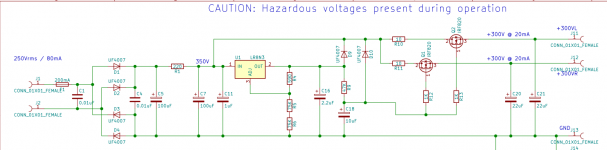
The high voltage supply is well regulated and is not very sensitive to even quite large variations in line voltage or load current as long as you are above the minimum load current required for proper operation (a couple of mA at most).
Super yours is broken, that 333V is approximately the voltage on the drains of Q1 and Q2.
Barring a catastrophic mistake the most likely culprit is D9 or D10 in the wrong way around or shorted.
Q1/Q2 pins - no shorts between pins. A short between pins 1 & 2 of either device will result in this behavior on both outputs.
The voltage on the anode of D9 should be a couple of volts higher than the output voltage. The voltage here should be within 3% of 300V.
Compare the voltage between the side of R1 closest to U1 input, with the voltage on the anode of D9, the difference should be at least 30V.
R12 and R13 are installed right?
U1 properly soldered, no cold solder joints, R4, R5, and R6 are correct values, soldered properly and neither R5 nor R6 are open.
It is unlikely anything has been damaged to this point so finding and fixing the error should result in normal operation.
The output voltage should be in the range of 291 - 309V (295 - 305 is preferred) under load. Mine is very similar to Dave's, and my line voltage varies from 117V - 125V depending on time of day and season.
Attachments
Merry Christmas and a new EQ
This is the first cut, but is easily implemented by jumpering R11, C2 needs to be replaced with 0.068uF.
The EQ plugs into pins 2, 3, and 4 of the connector provided for this purpose. You can wire something on tag strip temporarily and plug it into the connector.
The strain gauge is not noted for its flat frequency response as you can see from the post above.
There will be further improvements over time, no doubt.
I plan to eventually offer an EQ board that plugs in with this or a similar (further improved) equalizer..
I am still learning to use my new RTX analyzer, and have some noise pick up issues at 60Hz, 120Hz, and 180Hz.
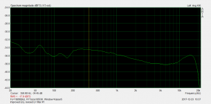
I would say that the equalized response of this particular 451C now falls within a +/-2dB window from 30Hz - 18kHz allowing for the LF issue. I also have a pretty fierce subsonic resonance in the 10Hz range of at least 10dB which is not shown.
The new EQ is a sufficiently significant improvement that I recommend those proficient with a solder iron and the old tradition of tacking bits and pieces together give it a try.
It is likely I will be able to improve this still further in the coming months, the current filter is the result of a couple of measurements I am too embarrassed to share and a few hours of analysis and modeling potential improvements.
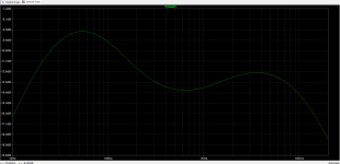
Note that the first graph is an actual FR measurement of a 451C on a Souther SLA-3 playing laterally recorded pink noise through the pre-amplifier with the new EQ. This is a significant if not earth shattering improvement over the default EQ in the pre-amplifier, unlike some previous attempts to address the same response issues this actually sounds better than the simplistic EQ.
This is the first cut, but is easily implemented by jumpering R11, C2 needs to be replaced with 0.068uF.
The EQ plugs into pins 2, 3, and 4 of the connector provided for this purpose. You can wire something on tag strip temporarily and plug it into the connector.
The strain gauge is not noted for its flat frequency response as you can see from the post above.
There will be further improvements over time, no doubt.
I plan to eventually offer an EQ board that plugs in with this or a similar (further improved) equalizer..
I am still learning to use my new RTX analyzer, and have some noise pick up issues at 60Hz, 120Hz, and 180Hz.
I would say that the equalized response of this particular 451C now falls within a +/-2dB window from 30Hz - 18kHz allowing for the LF issue. I also have a pretty fierce subsonic resonance in the 10Hz range of at least 10dB which is not shown.
The new EQ is a sufficiently significant improvement that I recommend those proficient with a solder iron and the old tradition of tacking bits and pieces together give it a try.
It is likely I will be able to improve this still further in the coming months, the current filter is the result of a couple of measurements I am too embarrassed to share and a few hours of analysis and modeling potential improvements.
Note that the first graph is an actual FR measurement of a 451C on a Souther SLA-3 playing laterally recorded pink noise through the pre-amplifier with the new EQ. This is a significant if not earth shattering improvement over the default EQ in the pre-amplifier, unlike some previous attempts to address the same response issues this actually sounds better than the simplistic EQ.
Attachments
I have another idea for a small change I am going to try. Will update accordingly.
Edit: Added an EQ change which may be of interest, only one component value has changed so far.
I probably need to work on the peaking a bit at 15kHz, but the response now falls within a +/-2dB window from 20Hz - 20kHz.
I may make further changes if I am able to squash down the peak at 15kHz a bit.
For the REV 02 I reduced the value of R3 from 56K to 33.2K.
For REV 03 I increased the value of C1 from 680pF and R5 from 68.1K to 75K. This basically retains the improvement in flatness from REV 02 while somewhat reducing the energy at 10kHz and above.
Currently I recommend either REV 01 or REV 03 as the best sounding combinations.
The topology allows for significant adjustments to be made in values, but the interactions are complex and it is a slow iterative process of simulating, changing the filter and measuring.
Attachments
Most excellent news on the new Eq!
I have been hearing what I would call groove noise that seems unrelated to circuit noise per se.
I don’t hear this type of signature with typical high quality LOMC,s and seems unique to the strain gage or is it simply the low end rise in your frequency graph ?
I,m hearing the same signature on 2 different tables with both Linear t. And pivoting arms.
Check your PM on a ? BTW
Regards
David
It seems to be a function of stylus geometry as much as anything. I have several different styli, the Panasonic OEM Shibata is significantly quieter, but not silent.
I will eventually make a plug in card for the EQ options discussed.
The first EQ presented is a significant improvement over the as delivered EQ particularly in terms of sound quality.
The second one offers significantly more HF energy and a slightly flatter overall response. The third one reduces the HF above 10kHz by more than 0.5dB while retaining the in band flatness of EQ 2. This is the one I am currently using.
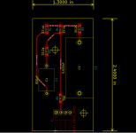
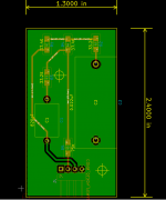
I have laid out a plug in card for the EQ I have discussed. It will accommodate any of the versions discussed here.
Resistors are 1206 SMD simply because the card was getting too big with TH parts. I recommend 1% or 0.1% thin film resistors from Panasonic or similar.
The capacitors should be high quality, for the 0.022uF a teflon REL cap would be suitable, and for the 820pF a good polystyrene is recommended.
The back of the board is ground plane for shielding.
It can be plugged directly in after making the recommended changes or it can be mounted a short distance away and a wired connector (or connection) can be used.
I have ordered 40 boards and need 8 for my own personal use leaving 16 sets for the crowd at large. A blank set of boards will run $8.00 plus postage. PM me if you are interested.
Parts for Revision 3 EQ:
0.1% 25ppm thin films from Digi-key, includes right angle connector. cart share: Digi-Key - Fast Add
C2 - REL RT or RTX 0.022uF/600V or TFT 200V/400V/600V matched and selected to 1% or better if possible.
C1 - MIAL or equivalent 680pF 5% 600V matched and selected to 2% or better if possible.
5% tolerance parts will be satisfactory in the event nothing else is available.
On the pre-amp board don't forget to jumper R11 and to replace C2 with a 0.047uF or 0.068uF 400V RT/RTX/TFT as budget and preference permits. Bass will be excessive if this capacitor is not replaced. (If your system is bass shy use the larger value otherwise it may be preferable depending on arm/cart combination to use the smaller value.)
Attachments
I have been listening for about a day now to the rev 3 EQ, it is definitely a significant step forward. Overall sound is more refined and the tonal balance is more neutral and balanced. Detail and imaging remains good as before, and overall less fatiguing to listen to.
The 451C seems to be a good choice for use on Linear Tracking arms and both of mine are on Souther LTAs.
The 465C is really best used on arms intended for low compliance cartridges like the SPU. I requires a sturdy stylus like the Bliss, the Panasonic EPS-451QD seems not to be a great match due to the high tracking force and the low compliance. It seems that an EPS-46ST is a better match, but the Bliss sounds better and has a Shibata or similar (line contact?) stylus.
I always suspected that my multimeter didn't work properly or the multimeter's battery is running low because all the voltages I got were on higher side. Even the AC was 125V. So, I found a cheap Radio Shack LCD multimeter. I got
302V at J13-J11 and 302V at J13-J12
24.4V at J13-J15
6.4V at J7-J9
Merry Christmas!
302V at J13-J11 and 302V at J13-J12
24.4V at J13-J15
6.4V at J7-J9
Merry Christmas!
Last edited:
 Well within the acceptable range and actually pretty close to the nominal (target) value. (Less than 1% off)
Kevin,
Is the cap 820 pf or 680 pf? I am going to order this one
Rel-Cap RTE, Sonic Craft
Does this one work?
The eq board can't come a better time. I am starting to assembly the phone boards and thinking possibly to acquire a pair of Lundahl transformers. I really hope the transformers can bring positive effect on the sound. In the meantime, I can have balanced outputs and switch the polarity.
Thank you for your time and efforts always!
- Home
- Source & Line
- Analogue Source
- Playing With Panasonic Strain Gauge Cartridges (And A Dedicated Phono Stage)