Thanks Kevin!
I found one with tighter tolerance. Everything else is same. However, I am bit confused. Please see the image. In your specs, these SMD are 1206 SMD. What I found are 0603, 0805. I don't know what these numbers mean. Are my selections ok?
I found one with tighter tolerance. Everything else is same. However, I am bit confused. Please see the image. In your specs, these SMD are 1206 SMD. What I found are 0603, 0805. I don't know what these numbers mean. Are my selections ok?
Attachments
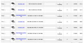
Search for "Thin film SMD resistor" on DigiKey
Then select Package / Case 1206 (3216 metric)
Tolerance 1% (and optionally 0.1%)
Stock status: check "In Stock"
Select 1 or more resistor values.
Click "Apply Filters"
Here is 10 ohm: RNCP1206FTD10R0 Stackpole Electronics Inc. | Resistors | DigiKey
Here is 100 ohm: RT1206FRE07100RL Yageo | Resistors | DigiKey
Here is 121 ohm: RNCP1206FTD121R Stackpole Electronics Inc. | Resistors | DigiKey
124 ohm OK to use thick film: RC1206FR-07124RL Yageo | Resistors | DigiKey
Here is 301 ohm: RNCP1206FTD301R Stackpole Electronics Inc. | Resistors | DigiKey
590 ohm OK to use thick film: RC1206FR-07590RL Yageo | Resistors | DigiKey
Here is 1K ohm: RNCP1206FTD1K00 Stackpole Electronics Inc. | Resistors | DigiKey
Nominal Voltage Values (For Testing)
Here are some voltage measurements on the audio cards. It is assumed that the power supply is producing approximately 6.3V, - 23.5V to -25.5V, and B+ is between 290V and 305V.
It is assumed that these boards have been built correctly and some basic testing has been done. This is not bring up. (Use a variac and/or ballast lamp to do that)
The assumption is that both channels are tested simultaneously, since all supplies are regulated it should not make a difference, but...
Install J5 and J6 jumpers so that they connect pins 2 & 3 together. Install jumper on J2 pins 2 & 3 unless you need more gain in which case install on 1 & 2. Note that running the board with no jumper installed or in the wrong position may damage the 6S3P.
Connect a 1K 1% resistor to the input of each channel before powering up!
There may be some variation in performance of the LSK389, pairs purchased at the same time should match each other quite well, but may not as I noted in a previous post quite perfectly match my intent.
Start by adjusting the pot to determine the highest and lowest current you can set, somewhere in that range should lie 4mA, if not choose the closest value to which both CCS may be set. (You can tweak the value of R20 later if needed) I was able to set both of mine to 3.9mA and one to just over 4mA and other just under.
The A23 battery if fresh should measure around 12.3V.
Measure the voltage across C1 - 11.65V
Measure voltage across R5//R18 - 13.53V
-24V supply - mine is 5% high at -25.2V - I may trim this later to something closer to 24V. (See previous post for recommendation on new build values and BOM revision.)
Measure the bias voltage on the side of C2 connected to the 6S3P-EV. Voltage should be in the range of -1.25V to - 1.5V.
The midpoint of the mu-follower/CCS (other side of C2) may vary significantly - with the particular 6CG7 fitted the voltage is 190V. With cartridge installed it will typically be about 10% - 15% lower. Note that R7 appears in series with the cartridge and in conjunction with the current subtraction CCS sets the operating point of the lower triode in the mu-follower/CCS. The value of R7 is not very critical and reducing it slightly to increase headroom in the CCS portion of the 6CG7 amplifier stage should not result in oscillation.
The 6S3P-EV plate voltage should be between 140 - 150V typically.
Note that a tolerance of several % either way should not result in a performance problem.
On the subject of tube rolling.
When you change tubes in the front end depending on how closely they match each other and the pair previously installed the subtraction current may need to be adjusted in order to maintain channel to channel balance.
I have been tube rolling and realized at a certain point that I had a pretty significant imbalance between the two channels and it turned out that one was off by 10% relative to the other.
R7 is currently 56 ohms in my second prototype, and cartridge current is almost 4mA. (4V across the 1K test resistor)
When setting or resetting the current allow the unit to warm up for about 5 minutes prior to setting the current value. Recheck in 30 minutes and readjust slightly if necessary. (Drift should be on the order of a couple of mV or less, and should be the same on both channels)
Kevin,
Can you do me a favor? I need your help to order some parts from Digikey. I am either not sure or could not find the parts.
Here is the list
1N4148 Diodes_THT_DO-41_SOD81_P7.62mm_Horizontal
Heatsink Heat sink: 35mm x 13mm x 38mm
HDR 1 x 4
HDR 1 x 3
HDR 1 x 3
DN2540N5-G TO_SOT_Packages_THT:TO-220_Vertical
DN2540N5-G
LSK389_SOIC SMD_Packages:SOIC-8-N
1.0K Potentiometers otentiometer_Trimmer_Bourns_3266Y
Two Heatsinks for phono section
Could I trouble you to send the links?
Thank you very much as always!
Jim
Can you do me a favor? I need your help to order some parts from Digikey. I am either not sure or could not find the parts.
Here is the list
1N4148 Diodes_THT_DO-41_SOD81_P7.62mm_Horizontal
Heatsink Heat sink: 35mm x 13mm x 38mm
HDR 1 x 4
HDR 1 x 3
HDR 1 x 3
DN2540N5-G TO_SOT_Packages_THT:TO-220_Vertical
DN2540N5-G
LSK389_SOIC SMD_Packages:SOIC-8-N
1.0K Potentiometers
otentiometer_Trimmer_Bourns_3266YTwo Heatsinks for phono section
Could I trouble you to send the links?
Thank you very much as always!
Jim
1K pot type 3266Y:
3266Y-1-102LF Bourns Inc. | Potentiometers, Variable Resistors | DigiKey
1N4148:
1N4148 Fairchild/ON Semiconductor | Discrete Semiconductor Products | DigiKey
DN2540:
DN2540N5-G Microchip Technology | Discrete Semiconductor Products | DigiKey
3 Pin Header:
61300311121 Wurth Electronics Inc. | Connectors, Interconnects | DigiKey
4 Pin Header:
61300411121 Wurth Electronics Inc. | Connectors, Interconnects | DigiKey
Heat Sink Phono PCB:
513102B02500G Aavid Thermalloy | Fans, Thermal Management | DigiKey
Heat Sink PSU PCB:
https://www.digikey.com/product-detail/en/aavid-thermalloy/529902B02500G/HS374-ND/1216379
Silpad Insulators, buy more than you need. I recommend doubling up on DN2540 and IRF820:
https://www.digikey.com/product-detail/en/bergquist/SP900S-0.009-AC-54/BER182-ND/307804
Shoulder washers for mounting TO-220 Devices:
https://www.digikey.com/product-detail/en/keystone-electronics/3049/36-3049-ND/40010
LSK389C is not sold by Digi-Key as I have previously stated, it is available here:
https://www.trendsetter.com/Transistor-p/lsk389c%20soic%208l.htm
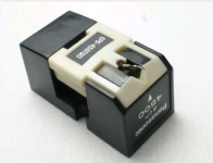
Here is an EPC-451C with an EPS-450QD stylus, located in Conn. With any used strain gauge cartridge you should expect to replace the stylus as a matter of course.
Vintage USED Panasonic EPC-451C and Panasonic EPS-450QD Strain Gauge Cartridge | eBay
I have noticed fairly massive increases in price in the past few weeks. There are now $600 strain gauges on eBay, although in fairness they do often come with a number of NOS OEM styli. Still hardly a bargain. Keep scrounging.
I scored a significantly challenged Panasonic EPC-450C which appears to have been abused at some point in its life. It's functional, but with the hopefully tired OEM stylus apparently had a distortion problem. There is a small crack in the back of the body that concerns me. I plan to start out with an inexpensive replacement stylus before investing in a better one. Choices of styli for the 450C are quite limited and good ones are a lot more expensive than with the 450CII - 465C. Shipped it came to $71 so if the gamble doesn't pay off I haven't lost a lot.
The EQ that will be required may be slightly different from the later ones, but that remains to be seen.
This was of interest because of the different packaging and much higher (theoretical) compliance.
The later ones I have seen to benefit from a considerable amount of mass loading. I am wondering how much of the LF rise is attributable to insufficient arm mass. Compliance is low, lower perhaps than even the DL-103, although I have not measured it.
The photograph is of the exact cartridge I purchased, but was scraped from the eBay listing. If you look very closely you can just make out the crack in back right corner of the housing. It does not go the whole way through.
It is anyone's guess as to what one of these sounds like, and if this one has internal damage I will probably never know.
I have wondered whether the compliance of the dampers and mounts has decreased significantly over the past 4.5 decades.
Attachments
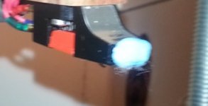
Those of you familiar with the 450CII and later series cartridges probably are aware that the strain gauges are mounted in the nose of the cartridge. It has come to my attention that touching this end of the cartridge results in noise. Damping the plastic in this area seems to improve HF smoothness and separation at least on a subjective level (of course it could be self suggestion).
I used about .2 gms of blue tak stuck right on the front edge of the nose, doesn't look particularly great, but I think it does something positive.
Can anyone corroborate this?
I used about .2 gms of blue tak stuck right on the front edge of the nose, doesn't look particularly great, but I think it does something positive.
Can anyone corroborate this?
Here is a shot of what I call "the blob" - it is aesthetically unappealing but it does seem to have an audible effect.
I realized since I installed this cartridge on this arm that the nose of the cartridge is quite microphonic, more so than most of the rest of the cartridge body. This observation arose because unlike the Souther the cartridge is easily accessible for touching.
Other lossy materials or things that increase the rigidity of the nose might be worth experimenting with.
Attachments
I do plan to take one apart when I get the 451 here so I can compare the 450c2 with each other on the same stylus.
Depending on any signifcant differences between them ( not expecting much ) one wil be put into a milled billet 6061 or 7075 t6 body with a similiar designed sound smith style design ( especially the stylus mounting arrangement)
There is a bad combination of low compliance coupled with plastic body and a push on stylus that just doesn't sit well with me
Maybe your concerns are just that area.
Regards
David
When I got my 451C, I looked at it. I don’t like the body and interchangeable stylus part. It is problematic. In my opinion, body is certainly needed to be upgraded. However, the main problem is its stylus. The way of stylus clipped on the body is simply not acceptable. For me, it may be next project. I need to get the phono work first.
- Home
- Source & Line
- Analogue Source
- Playing With Panasonic Strain Gauge Cartridges (And A Dedicated Phono Stage)