Hi,
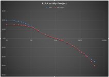
I'm having some trouble with the RIAA on a project I've been assembling. Everything works as it should but the bass is down. It uses a passive RIAA network and while there are a lot of online calculators, I really need some help to know which RIAA components (R7, R8, C2 or C4) to change and whether to increase or decrease.
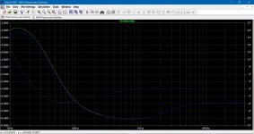
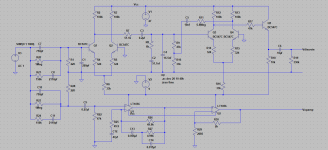
I've attached the schematic and my RIAA plot.
Cheers!
I'm having some trouble with the RIAA on a project I've been assembling. Everything works as it should but the bass is down. It uses a passive RIAA network and while there are a lot of online calculators, I really need some help to know which RIAA components (R7, R8, C2 or C4) to change and whether to increase or decrease.
I've attached the schematic and my RIAA plot.
Cheers!
Attachments
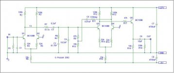
Not an easy circuit to analyse, but it appears that LF boost depends on the input impedance of the second stage, which depends on the current gain of Q3. R9 is boostrapped so that will not contribute very much to input loading. As BJT current gain is a very poorly controlled characteristic then in this sense it is quite a poor circuit.
Try putting a higher gain transistor for Q3.
Try putting a higher gain transistor for Q3.
I forgot to mention that I used BC549 transistors instead of BC109. I measured the hfe of all the BC549's and got about hfe=600 for Q3. I could try a higher gain transistor but would dropping R7 cause my bass response to increase?
Are their any high gain suggestions for the transistors?...I'm mostly a tube guy....
Yes, I would not be surprised if it is from the 1970's!
Are their any high gain suggestions for the transistors?...I'm mostly a tube guy....
Yes, I would not be surprised if it is from the 1970's!
I am calculating ~ +13V on the collectors of the input LTP.
Is that about right?
It looks like a similar voltage appears on the collectors of the second stage LTP.
Is that about right?
That would give about 2mA through the EF output stage.
The whole circuit runs at extremely low current.
Would it work better with some higher currents in each stage?
Is that about right?
It looks like a similar voltage appears on the collectors of the second stage LTP.
Is that about right?
That would give about 2mA through the EF output stage.
The whole circuit runs at extremely low current.
Would it work better with some higher currents in each stage?
I'm using this, which has the advantage of using standard parts:
http://www.diyaudio.com/forums/anal...improving-disco-mixer-mid-fi-performance.html
post 5.
I don't know how accurate it is but it has plenty of bass.
besides mc33078 it probably works as well with NJM2068 or NE5532. I'm using a single 18v supply from a car race wall transformer, and making the analog ground with two 7.8 v zeners per an earlier post.
Dip project boards are useful for spreading the wires out enough where you can solder them.
Hi Molly, I don't have a simulator. I'm interested in your first simulation and the rising bass. This is the opposite of what I'm getting. I wonder if it is due to c5 being 10mf in your Sim (vs 0.01mf in the original circuit).
I will have to take a closers look tonight when I get home...
Thanks for your efforts to load these a simulator.")
I will have to take a closers look tonight when I get home...
Thanks for your efforts to load these a simulator.
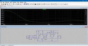
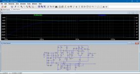
So here is C5 at 0.01uf and 10uf, both traces on the one chart. It makes virtually no difference.
Edit... C5 already was 0.01uf. I entered it as 10nf. You can see the value makes little difference here.
(If you are interested in running the simulation then my sig line tells all)
Edit... C5 already was 0.01uf. I entered it as 10nf. You can see the value makes little difference here.
(If you are interested in running the simulation then my sig line tells all
)Attachments
I don't know what to suggest on this. The circuit itself wouldn't seem to be at fault.
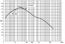
Phono preamps and RIAA specs are something alien to me but I believe the RIAA was changed in the 80's ? Does that affect the encoding as well as the decoding ? Could you be chasing a non existent issue here.
Here is a clearer image of the set up as well.
Phono preamps and RIAA specs are something alien to me but I believe the RIAA was changed in the 80's ? Does that affect the encoding as well as the decoding ? Could you be chasing a non existent issue here.
Here is a clearer image of the set up as well.
Attachments
- Status
- This old topic is closed. If you want to reopen this topic, contact a moderator using the "Report Post" button.
- Home
- Source & Line
- Analogue Source
- RIAA Help