I love vintage gear and I have a Beogram 1200 with a failing stylus suspension. The major drawback with the old Beograms is the B&O proprietary cartridges and stylus, the fact that B&O doesn't support them anymore, that even ridiculously expensive NOS might fail due to aged stylus suspension and the inability to replace the proprietary tonearm, BUT they sure are nice to look at. ")
Anyway, I use my Beogram 1200 almost daily so I really want a way to at least replace the stylus, but how to do that when there are no new ones, no one is rebuilding them, nothing else fit the cartridge and you can't replace the tonearm? Build your own replacement cartridge and stylus?
I know it's a crazy endeavor but I started to play with the idea. I'v done some minor changes to some of my vintage gear but I always make sure to save all original parts and also secure a way to reverse any modifications back to stock. How could I getaway with it on a Beogram 1200?
I started to search the net. Surely someone must have made something close to it right? But I came up with nothing, what a surprise! I didn't let that stop me and I am now documenting my effort in case anyone else search for something similar.
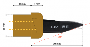
First up, what are the constraints? The Beogram 1200 tonearm is pre bent to some 20 degrees. It's a thin aluminum tube, 13 mm outer diameter and 11 mm inner diameter. The original cartridge is 30 mm long including stylus and it weight 7.5 gram.
My first thought was to make an adapter but the pre-bent arm makes it difficult, most cartridges are made to fit a straight arm and it would totally kill it aesthetically. Next thought was to find suitable donor, something that would fit good enough as a starting point.
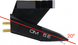
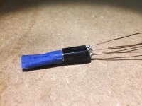
The 20 degree pre-bent arm got me thinking about the old Ortofon Concorde and that thought led me to the Ortofon OM cartridge. It can be had for a reasonable amount of money with the 5E stylus and it's well supported with replacement styluses. I decided to give it a try and ordered one from Germany.
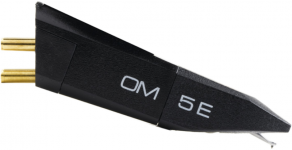
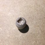
My plan was to take the Ortofon OM 5E as seen on image 1, take away everything except whats in image 2 and make something like image 3.
Anyway, I use my Beogram 1200 almost daily so I really want a way to at least replace the stylus, but how to do that when there are no new ones, no one is rebuilding them, nothing else fit the cartridge and you can't replace the tonearm? Build your own replacement cartridge and stylus?
I know it's a crazy endeavor but I started to play with the idea. I'v done some minor changes to some of my vintage gear but I always make sure to save all original parts and also secure a way to reverse any modifications back to stock. How could I getaway with it on a Beogram 1200?
I started to search the net. Surely someone must have made something close to it right? But I came up with nothing, what a surprise! I didn't let that stop me and I am now documenting my effort in case anyone else search for something similar.
First up, what are the constraints? The Beogram 1200 tonearm is pre bent to some 20 degrees. It's a thin aluminum tube, 13 mm outer diameter and 11 mm inner diameter. The original cartridge is 30 mm long including stylus and it weight 7.5 gram.
My first thought was to make an adapter but the pre-bent arm makes it difficult, most cartridges are made to fit a straight arm and it would totally kill it aesthetically. Next thought was to find suitable donor, something that would fit good enough as a starting point.
The 20 degree pre-bent arm got me thinking about the old Ortofon Concorde and that thought led me to the Ortofon OM cartridge. It can be had for a reasonable amount of money with the 5E stylus and it's well supported with replacement styluses. I decided to give it a try and ordered one from Germany.
My plan was to take the Ortofon OM 5E as seen on image 1, take away everything except whats in image 2 and make something like image 3.
Attachments
Last edited:
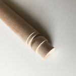
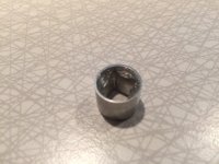
I contemplated a suitable material but ended up using a 14 mm birch dowel rod. I liked the idea of something in wood and it is quite easy to machine so I stuck it in the lathe and made a couple of what you find in image 1.
I lack a small enough coordinate table to I finished it off with a Dremel until it looked like image 2.
I had to take off the connectors sticking out at the wrong angle on what was left of the cartridge and I then soldered some solid copper wires on what was left of them, picture 3.
I desoldered the socket for the original cartridge and that left me with a hollow piece of the tonearm 11 mm in diameter and at least 9 mm long. I made my wooden adapter fit perfectly in the tone arm, glued what was left of the OM cartridge to the wooden adapter and soldered the tonearm wires to the trimmed copper wires from my butchered OM cartridge, picture 4.
Attachments
Last edited:
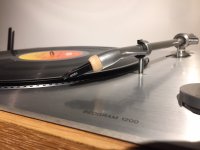
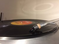
It now started to look quite decent, it actually looked like it could work, image 1.
But it can't be that easy can it? The original cartridge weight 7.5 gram my "Francofon" weight only 3 gram and the B&O tonearm is very inflexible when it comes to adjust anything except weight of the original cartridge...
I took some tape and fastened a nut with the right weight (around 4 grams) to the arm just to try it out. It sounded perfectly but how could I fix this?
What I ended up doing was probably not the easiest route to take but it was quick. I took a plunge base router with a 13 mm router bit and routed a hole in a piece of MDF. I then fixed another piece of MDF under it and then poured a melted mixture of tin and led into this "mold". I then drilled a hole in the middle of this quite heavy piece of metal, and filed it by hand until it fit over the cartridge. It ended up just shy of 5 gram, picture 2.
Picture 3 is the final result. It works perfectly and I can now continue to use my Beogram 1200 AND buy cheap new styluses when needed. This was just a proof of concept and I will do it a bit differently if I ever have to replace the cartridge. I would probably fuse wood and metal and then machine it into a nicer shape on the lathe. I would also consider fusing metal and some black epoxy instead of wood. There are plenty of ideas in my head on how to do this better but I will now just kick back and enjoy some records on my newly modded Beogram 1200
Ps. No original parts were harmed during this experiment.
Attachments
Last edited:
Thank you Arch, it was well worth €30 (cost of the Ortofon OM 5E) and it only took a couple of hours to make (it was a fun project too).Very smart, wonderful idea.
Thanks bulgin, is there a way to repair a failed stylus suspension on an original B&O "bullet" cartridge?Very nice and inventive ...
I have quite a few of those old cartridges and the means to repair them.
Regards / Rob
Hi EmuMannen,
Most impressive work, and thank you for proving that this is possible! Great inspiration.
I'm trying to copy the trick on my Beogram 1203 (mostly same design), although I'll be 3D-printing the adapter instead of powering up my lathe. One question up front: In IMG_1376 it looks like you've soldered the two returns (blue, green) together with the ground/earth cable. Is that correct, and is it recommendable? I know that blue/green are connected inside the turntable anyway, but the ground/earth is kept separate in the original design as well as on modern turntables and RIAAs. I'm rather inclined to assume that there's a good reason for that. Would you care to comment on that? Thanks.
Regards, Rasmus
Thanks for your kind words and for reminding me about this build. I want to go back and redo this work and I was also planning to 3D print, then make a silicon mold and finally cast it in metal.Hi EmuMannen,
Most impressive work, and thank you for proving that this is possible! Great inspiration.
I'm trying to copy the trick on my Beogram 1203 (mostly same design), although I'll be 3D-printing the adapter instead of powering up my lathe. One question up front: In IMG_1376 it looks like you've soldered the two returns (blue, green) together with the ground/earth cable. Is that correct, and is it recommendable? I know that blue/green are connected inside the turntable anyway, but the ground/earth is kept separate in the original design as well as on modern turntables and RIAAs. I'm rather inclined to assume that there's a good reason for that. Would you care to comment on that? Thanks.
Regards, Rasmus
The cables, I think I kept them as on the original design, blue and green apart but I can’t recall what I did with the ground wire? I remember doing a lot of research on different ways to connect the wires, pros and cons since the cartridge only has four pins and there is five wires counting ground. The original mount and cartridge got some metal where the ground wire is attached. I might have ended up soldering the ground wire either to blue, green or both. It is currently in my garage stacked in a plastic container (with a bunch of other, fully restores turntables). I will try to do an inspection if I manage to dig it out of the pile (I guess it’s in the bottom of one of the stacks)…
Don't go through too much trouble for the wiring. I believe a safe choice is to keep the ground to the tonearm only - isolated from the cartridge leads; I just wanted to hear, if you were certain of something else
I don't have equipment for molding/casting myself - sounds like a really nice solution. Is this something you'll be doing anytime soon? I'd be very happy to purchase a cast from you
I'm attaching my 3D model. Maybe it can be of help. I'm using Blender (mostly because I was familiar with Blender already before getting my first 3D-printer, and instead of learning a CAD program, I just stuck to what I knew). The cut-aways for the OM cartridge are currently with zero margin, so some adjustment of the model is necessary to make the cartridge fit in the hole - either in the design or mechanically after manufacturing. As that margin will depend on printer, material, technique, etc, I didn't want to apply it before uploading the file.
Attachments
- Home
- Source & Line
- Analogue Source
- DIY replacement cartridge and stylus for a Beogram 1200