I don't think the cart can be placed in parallel with the inverse RIAA (IRN) like you show.
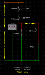
Might be an idea to scale your IRN impedances DOWN by a factor of 10 so that R3 becomes 110 Ohms and then to place your cart inductance in series with the output to the 47k input load resistor. You could also place additional resistance in series with the inductor to more accurately simulate the cart DC resistance.
Here is a short write-up for further info An Accurate Inverse RIAA Network
The circuit in post 1, with or without buffer, does not represent a cartridge so it is not clear to me why a cartridge-equivalent circuit has been tacked on the end. To get some version of reality you would need to put the opamp output in series with the inductance, not parallel. Then add the effect of mechanical resonances etc.
To All.
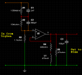
What i'm trying to do, is sim/test/see how a pre emphasised cart signal Actually reacts to the RIAA de emphasis, when Actually loaded with a cart.
As i see it, just testing a phono stage with an IRN circuit, without a cart, doesn't take into account the effects the cart has. Therefore, a perfectly seeming flat RIAA stage, could be anything but !
*******
@ Bonsai
I've now tried the cart, L1 & R4, placed in both series & parallel connection to the SigGen output instead. I don't see any frequency etc variances doing this. Is that ok to place there ?
Scaling IRN impedances DOWN by a factor of 10 made a big difference")
Thanx for the "Accurate Inverse RIAA Network" info
@ lcsaszar
That's the oddness i noticed.
@ rayfutrell
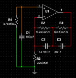
Those IRN component values are identical to what i originally simmed. Thanx for the APT heads up I was able to get a PDF of the manual. Very interesting, & full of useful info & data !
@ DF96
I placed it there initially, as i thought that's where it would go !
Further to what i just mentioned to you, a cart is normally connected with one pin to phono common, & the other pin to phono input. To me that appears to be a parallel connection, not series ?
That's a whole other ball game
What i'm trying to do, is sim/test/see how a pre emphasised cart signal Actually reacts to the RIAA de emphasis, when Actually loaded with a cart.
As i see it, just testing a phono stage with an IRN circuit, without a cart, doesn't take into account the effects the cart has. Therefore, a perfectly seeming flat RIAA stage, could be anything but !
*******
@ Bonsai
I don't think the cart can be placed in parallel with the inverse RIAA (IRN) like you show.
I've now tried the cart, L1 & R4, placed in both series & parallel connection to the SigGen output instead. I don't see any frequency etc variances doing this. Is that ok to place there ?
Scaling IRN impedances DOWN by a factor of 10 made a big difference
Thanx for the "Accurate Inverse RIAA Network" info
@ lcsaszar
L1-R4 are still there without the buffer? Then they represent a frequency-dependent load to the inverse RIAA network.
That's the oddness i noticed.
@ rayfutrell
Page 52 of the APT HOLMAN preamp service manual has a buffered inverse RIAA network using standard value components that they claim is accurate within +- 0.1 dB.
Those IRN component values are identical to what i originally simmed. Thanx for the APT heads up
I was able to get a PDF of the manual. Very interesting, & full of useful info & data !@ DF96
The circuit in post 1, with or without buffer, does not represent a cartridge so it is not clear to me why a cartridge-equivalent circuit has been tacked on the end
I placed it there initially, as i thought that's where it would go !
To get some version of reality you would need to put the opamp output in series with the inductance, not parallel.
Further to what i just mentioned to you, a cart is normally connected with one pin to phono common, & the other pin to phono input. To me that appears to be a parallel connection, not series ?
Then add the effect of mechanical resonances etc.
That's a whole other ball game
A cartridge is designed to give a roughly flat response when loaded by the manufacturer's recommended load, typically 47k with some parallel capacitance. You cannot check that in simulation because part of it is the mechanical response.
The RIAA equalisation is intended to undo the RIAA imposed at cutting time, with the adjustment of a velocity transducer. This you can check in simulation, if you wish.
These are two separate things. People often confuse them, or say things like 'the frequency response of the preamp depends on the cartridge impedance so I need to model both together'. Note that the latter may be true, but deeply misleading for a newbie (and, perhaps, some 'gurus' too). If you provide the right cartridge load then it will provide a flat voltage at the preamp input. Therefore you need to ensure that the preamp provides the correct RIAA response when driven from a voltage source. Given all this, I believe you have a mistaken aim.
However, if you really want to model the cartridge electrical response (for reasons I cannot fathom) then you need to inject your signal voltage at the right place. This is between ground and the 'grounded' end of the cartridge inductance. In your circuit as shown, the cartridge model is driven from zero impedance (the output of the opamp) so can have no effect at all. In the unbuffered version you are merely seeing the interaction between a cartridge model (wrongly applied) and a particular anti-RIAA network - which combination is of no interest to anyone at all.
Zero D,
You must put the cartridge in series with the OUTPUT of your IRN - I was not clear enough.
A typical inductance for an MM cart is 600 mH and a DC resistance 500 ohms. Again, place these in series with the output of your IRN and before your 47k load.
Putting your cart in series with the IRN output like this will let you test the noise contribution of the cart. If you add the cable capacitance and RIAA amp input capacitance, you can also check the response anomolies due to these parasitic so - but only do that once you have confirmed your RIAA is working correctly.
Last edited:
Originally Posted by DF96
A cartridge is designed to give a roughly flat response when loaded by the manufacturer's recommended load, typically 47k with some parallel capacitance.
It can't be flat = straight line, due to the IRN pre emphasis ! If it was flat we wouldn't need the RIAA circuit after the cart input. If you mean, the response shouldn't deviate much from that, then that's different.
You cannot check that in simulation because part of it is the mechanical response.
Well, that's were we all have a BIG issue then, if we don't actually know what's happening !
The RIAA equalisation is intended to undo the RIAA imposed at cutting time, with the adjustment of a velocity transducer. This you can check in simulation, if you wish.
I thought you'ld realise, i already know that, due to what i've mentioned earlier.
In the unbuffered version you are merely seeing the interaction between a cartridge model (wrongly applied) and a particular anti-RIAA network - which combination is of no interest to anyone at all.
Well i think it is of interest. If the pre emphasis on a record presented to the cart, is altered due to the cart, then even a perfect RIAA stage won't give a true response. That's why i'm trying to see if we can engineer a more true response, by simming & testing etc. What's wrong with wanting to do that ?
Originally Posted by Bonsai
You must put the cartridge in series with the OUTPUT of your IRN - I was not clear enough.
OK, did do.
A typical inductance for an MM cart is 600 mH and a DC resistance 500 ohms. Again, place these in series with the output of your IRN and before your 47k load.
When i do, i get an awful response ! Please sim it & let me know what you see
i get an awful response !
What is your phono circuit? This means the preamp's input interacts with the cartridge's source impedance.
See: Holman, 'New Factors In Phonograph Preamplifier Design'
Last edited:
I mean flat as in accurate velocity transducer i.e. 6dB/octave slope.Zero D said:It can't be flat = straight line,
If it was a displacement transducer then we would still need RIAA, but it would be a different RIAA with a mid-band shelf and an LF rolloff.If it was flat we wouldn't need the RIAA circuit after the cart input.
Yes, that is my point. We don't know what the mechanical response is, so there is no point in modelling the electrical response in isolation except as as an exercise with the potential to seriously mislead both newbies and 'gurus'. However, if for some strange reason we want to model the electrical response then it helps if we use the right circuit instead of the wrong circuit.Well, that's were we all have a BIG issue then, if we don't actually know what's happening !
Two things wrong with that:Well i think it is of interest. If the pre emphasis on a record presented to the cart, is altered due to the cart, then even a perfect RIAA stage won't give a true response. That's why i'm trying to see if we can engineer a more true response, by simming & testing etc. What's wrong with wanting to do that ?
1. you have not included the mechanical response
2. you have not got the right circuit to model the electrical response
There are two ways to get a good response from an MM:
1. ensure that the preamp applies the correct load, and ensure the preamp correctly applies RIAA equalisation to a voltage input - this is the easy way
2. design the preamp so the input impedance (and hence the cartridge load) varies significantly with frequency (e.g. due to feedback), and the feedback (and hence RIAA response) varies due to cartridge impedance, and then somehow mix and match the two problems to get the right overall result - this is the hard way
Some people get mixed up between these two methods; I suspect the OP may be one of these. Some 'gurus' get mixed up too - this is a bit like those who make a similar mistake at the other end of the audio system and want to distinguish between speaker impedance and speaker back-emf (when it is back-emf which defines impedance!).
Here's a test circuit i used.
That's fine. A real circuit would usually need a large capacitor, 100uF - 470uF,
between R3 and ground, to minimize the output DC offset.
Which op amp is chosen for the U1.
Last edited:
Originally Posted by rayma
That's fine.
A real circuit would usually need a large capacitor, 100uF - 470uF,
between R3 and ground, to minimize the output DC offset.
Yeah i realise that
Which op amp is chosen for the U1.
OP27
When i do, i get an awful response !
Can you post the response?
@ rayma et al
After tinkering with it again, i tried the Cart Sim components in all 3 positions. The other 2 positions naturally had the links connected together in each case. All 3 now do not affect the response as i found before ! I'm not sure why this is, maybe initially a component was a different value, or something ? Anyway, thanx to All for your input etc
After tinkering with it again, i tried the Cart Sim components in all 3 positions. The other 2 positions naturally had the links connected together in each case. All 3 now do not affect the response as i found before ! I'm not sure why this is, maybe initially a component was a different value, or something ? Anyway, thanx to All for your input etc
Attachments
Last edited:
- Status
- This old topic is closed. If you want to reopen this topic, contact a moderator using the "Report Post" button.
- Home
- Source & Line
- Analogue Source
- Inverse RIAA Testing