Kids came over last night so no energy left for soldering so looking back at this. I realised I used the term 'self-inductance' where Rod Elliot used 'Semi-inductance'. Happy to use another term if people prefer. The question then comes as to whether this can account for the midband dip some cartridges see, rather then the mechanical resonance that is 'perceived wisdom' and started this thread. Looking at George's plots from post 279 I think there is enough information to answer that as we can calculate the deviance from a pure L+R series combination and see what that would do to the frequency curve.
For examples of midband dip see here New Lamps for Old . Some distortion vs level graphs to mull as well, albeit only at 315Hz. I am sure we have discussed this before and started re-reading the thread from page one, but the intriguing part is that the shures all show a teeny (1dB) midband dip and small HF peak, whereas the Ortofon 2M shows no midband dip and a much larger resonant peak. And the Rega is well, bleh. Now all of these are same guy, same test record, same loading so hopefully something we can infer, esp as George has his plots of the M97 to compare.
Then I compared Zev's measurement Shure V15V - ZevAudio . Now I think he has got a bit carried away claiming a 0.7dB dip is from mech effects, but he is showing some severe HF effects. Guessing he has a boutique phono stage. He also hasn't stated which HFN test record he has, but I have the first and george has the second so between us we can work this out.
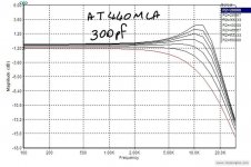
Also note the AT440MLa Audio Technica AT440MLa - ZevAudio Now LD's simulation of this cartridge does not show this dip, based on a simple LRC model.
Other thing I did was look at errors in the Aurak if the load resistor is wrong. This was probably obvious to those versed in the art, but above the turnover point its tracks RIAA perfectly and the error can be viewed as a fixed offset below the turnover point. Worst case in my initial checks using a fixed 150 Ohms was 0.8dB. from 348Hz down. I can live with that as my little room is modal by then so I have bigger issues to sort") .
.
For examples of midband dip see here New Lamps for Old . Some distortion vs level graphs to mull as well, albeit only at 315Hz. I am sure we have discussed this before and started re-reading the thread from page one, but the intriguing part is that the shures all show a teeny (1dB) midband dip and small HF peak, whereas the Ortofon 2M shows no midband dip and a much larger resonant peak. And the Rega is well, bleh. Now all of these are same guy, same test record, same loading so hopefully something we can infer, esp as George has his plots of the M97 to compare.
Then I compared Zev's measurement Shure V15V - ZevAudio . Now I think he has got a bit carried away claiming a 0.7dB dip is from mech effects, but he is showing some severe HF effects. Guessing he has a boutique phono stage. He also hasn't stated which HFN test record he has, but I have the first and george has the second so between us we can work this out.
Also note the AT440MLa Audio Technica AT440MLa - ZevAudio Now LD's simulation of this cartridge does not show this dip, based on a simple LRC model.
Other thing I did was look at errors in the Aurak if the load resistor is wrong. This was probably obvious to those versed in the art, but above the turnover point its tracks RIAA perfectly and the error can be viewed as a fixed offset below the turnover point. Worst case in my initial checks using a fixed 150 Ohms was 0.8dB. from 348Hz down. I can live with that as my little room is modal by then so I have bigger issues to sort
.Attachments
OK soldering is nearly completed and I must write to Russ asking him to open out the IO holes a litte as they were effectively press fit for the power. It's not the prettiest* due to a couple of last night ordering sessions where I picked low tempco r*esistors without checking their girth, but at least everything is matched to a sane level**. Last resistor to fit is the gain resitor (R23 on Hans schematic). Now I have some odd gain requirements as I'll have cartridges from 4mV to 20mV and ADC inputs from 2V to 8V. Would be nice to have 6 switchable gain steps. Looking at the circuit doesn't suggest that an extra 3-6" of wire in that location would have any ill effect, but no direct experient of these devices and wondered if anyone here did?
Now to test!. LD have questions for you on final setup. PM or email best?
*Pics to follow.
** Critical resistors are as close to 0.01% as my test rig would allow. I figured worth seeing if good balance actually does anything.
Now to test!. LD have questions for you on final setup. PM or email best?
*Pics to follow.
** Critical resistors are as close to 0.01% as my test rig would allow. I figured worth seeing if good balance actually does anything.
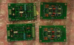
Pics just to show I have actually been doing some soldering. Need to find my hot glue gun then work out best way to test these with the limited setup currently to hand.
Other than the RIAA and gain modifications the rest goes together quite easily. I think as the number of people who would actually do something as bonkers as this is limited from an assembly point of view we can claim this as doable. I think a PCB for the single ended version would be good. I might challenge myself to do a layout for that sometime.
Other than the RIAA and gain modifications the rest goes together quite easily. I think as the number of people who would actually do something as bonkers as this is limited from an assembly point of view we can claim this as doable. I think a PCB for the single ended version would be good. I might challenge myself to do a layout for that sometime.
Attachments
OK a particularly dumb moment today. I have been fretting that I have too much gain in the preamp. The miniDSP has an 8V balanced input which gives me some headroom, but I hope to someday move to the TI EVM board that Wayne recommended on another thread with is half that. One of the combinations (at least until I can work out how to get the S-120 stylus to actually fit into a superOM body) is the S-120 body series wired for mono, which gives a whopping 20mV in that configuration. So I finally sat down and calculated the gain across the different parts until with a loud clunk the penny dropped that the cartridge series resistance directly affects gain and so, to a first order spherical cow calculation the series strapped input will give the same output as the stereo configuration. Additionally because output is generally related to turns on the coil (give or take magnet differences) the S-120 will give same output as the OM in stereo. I feel so silly...
I have been doing listening tests between CD and LP to find the RIAA values to get great sound. it would be handy if a circuit was posted that allows a signal generator to feed the cart with a signal that duplicates a sweep LP.
At one point I had the 40hz response up 5db, addictive on SOME recordings less so on others. Treble response is way up. I am attributing that to the flat NPN head amp with 120k 100pf loading
Bullshurv, are you using a MM or MC cartridge ?
At one point I had the 40hz response up 5db, addictive on SOME recordings less so on others. Treble response is way up. I am attributing that to the flat NPN head amp with 120k 100pf loading
Bullshurv, are you using a MM or MC cartridge ?
Last edited:
I am my own worst enemy. I recently came across a very good deal on a classiC AT cartridge from the 70s, the AT25. This interested me because of the stylus mounting system, where the cantilever is attached to a machined block which is screwed onto the cartridge body. Nice and studly and different, and possibly unecessary . But I wanted.
Of course I didn't check the generator specs in my 'new toy' frenzy. It's unusual in being a toroid rather than the paratoroid of later models. Apparantly hand made which is why this was dropped. It's an oddball. 85mH and 240R DC, and 2.2mV in voltage mode. Should be ideal for the Aurak concept similar to Grado. Darn need another phono stage
. But I wanted. Of course I didn't check the generator specs in my 'new toy' frenzy. It's unusual in being a toroid rather than the paratoroid of later models. Apparantly hand made which is why this was dropped. It's an oddball. 85mH and 240R DC, and 2.2mV in voltage mode. Should be ideal for the Aurak concept similar to Grado. Darn need another phono stage
Attachments
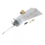
I am my own worst enemy. I recently came across a very good deal on a classiC AT cartridge from the 70s, the AT25. This interested me because of the stylus mounting system, where the cantilever is attached to a machined block which is screwed onto the cartridge body. Nice and studly and different, and possibly unecessary
Of course I didn't check the generator specs in my 'new toy' frenzy. It's unusual in being a toroid rather than the paratoroid of later models. Apparantly hand made which is why this was dropped. It's an oddball. 85mH and 240R DC, and 2.2mV in voltage mode. Should be ideal for the Aurak concept similar to Grado. Darn need another phono stage
Hi Bill,
Do you want me to recalculate the components for your balanced Aurak for this new AT25 toy ?
Hans
I recently came across a very good deal on a classic AT cartridge from the 70s, the AT25. This interested me because of the stylus mounting system, where the cantilever is attached to a machined block which is screwed onto the cartridge body.
In most MM cartridges, the same polepiece lamination extensions that allow the moving magnet to convey its flux modulations into the coils, double up as the primary mechanical mounting for the cantilever assembly.
Although the coil structure of the AT22, 23, 24 and 25 are encased in a permalloy can typical of most MMs, a diecast wall runs vertically through the entire can. The toroidal coils are secured to either side of the wall, which is also what the cantilever block is screwed to.
The AT22, 23, 24 and 25 will play even without the can, whereas with nearly any other MM cartridge (which lack the internal wall), everything would be in pieces.
R4/R6 = 14K3 (was 49k6)Hi Hans,
I should say no and work it out for myself, but if you have time yes please.
R3/R5 = 73k6 (was 38k3)
R1/R3 = 13.5
(R1+R3) = Pi*L-Rc = Pi*85-240 = 27 Ohm
Hans
Bill, I can’t help with the compliance thread you're seeking. However, I question any “rule” purporting to relate 100Hz “compliance” to that at 10Hz. First of all, what is meant by “compliance”? A stylus suspension has mechanical impedance – a complex value having a real (springiness) and an imaginary (damping) part. Both real and imaginary parts can vary with frequency and temperature.
At issue is the mechanical admittance (reciprocal of impedance). At 10Hz it’s the real part of admittance (compliance) that’s of practical interest since it governs tonearm resonance frequency. But at 100Hz, it’s the total admittance that’s of interest since that limits maximum modulation amplitude that can be tracked.
My understanding is that 10Hz compliance values are typically determined by measuring stylus resonance frequency when loaded with a known mass (i.e., tonearm effective mass) at specified VTF. I’m not sure how 100Hz values are determined experimentally. (Perhaps by modulation tracking limits? Or by exciting the stylus mechanically?)
Refer to my post #1222 and the curves showing mechanical properties of butyl rubber, typical for a stylus suspension bung. Both the real (springiness) and imaginary (damping) values can be derived from these curves. One could compare 10Hz and 100Hz values and formulate a “rule” to relate them. But this rule would only be valid at one temperature.
If the stylus design includes a metal tie wire, additional suspension stiffness in introduced, essentially invariant with frequency and temperature.
Sometimes a “static compliance” is specified. Is this determined by direct measurement of stylus deflection under VTF load? i.e., “0Hz compliance”? Not very meaningful for judging either tonearm resonance frequency or modulation trackability.
Didn't see this answered, so ...
As I understand it (with some backstory) ...
Japanese manufacturers specify 100 Hz at 10 –6 cm/dyne
European manufacturers specify 10 Hz at 10 -6 cm/dyne
American manufacturers specify 0Hz or "static compliance"
The 10 -6 cm/dyne describes the speed of the test LP while playing a 10 Hz or 100 Hz test tone.
The 0Hz means just that ... it's measured statically, or put another way, with no LP rotating. So your guess is probably correct (not sure how else they could do it).
Last edited:
Dept of 'did I think this through' time. When I started on the balanced preamp (mumble) months ago I only had one arm I was considering using and 2 types of cartridge with the ability to lift the ground tab and earth to the headshell. Since then feature creep means I have more arm and cartridge combinations and I've got a couple of odd edge cases
1. Cannot access the ground tab (ortofon/SME30H armwand)
2. Cannot gnd via tonarm (sme 3009 series 3)
In these cases as there is no conductive path from cartidge to tonearm I have the options of either suck it and see or run single ended. And here my brain is failing me yet again.
Assume single ended operation with the negative lead grounded before the preamp. Kirchoff says that the return current has to go back to the cartridge, so that suggests that I can leave the split load resistors and things will still function as expected. But that feels wrong. I'm either over thinking this or missing something.
How vital is no gnd connection being available for the functioning of your Cart?Dept of 'did I think this through' time. When I started on the balanced preamp (mumble) months ago I only had one arm I was considering using and 2 types of cartridge with the ability to lift the ground tab and earth to the headshell. Since then feature creep means I have more arm and cartridge combinations and I've got a couple of odd edge cases
1. Cannot access the ground tab (ortofon/SME30H armwand)
2. Cannot gnd via tonarm (sme 3009 series 3)
In these cases as there is no conductive path from cartidge to tonearm I have the options of either suck it and see or run single ended. And here my brain is failing me yet again.
Assume single ended operation with the negative lead grounded before the preamp. Kirchoff says that the return current has to go back to the cartridge, so that suggests that I can leave the split load resistors and things will still function as expected. But that feels wrong. I'm either over thinking this or missing something.
My cart is fitted in wood and does not even has a gnd connection.
It would be a shame after all your balanced efforts to go SE.
Hans
Bill,
When there is an absolute need to make a gnd connection, you can either leave the split resistors as they are, or replace the resistor in the hot line by one with the double value and reduce the one connected to gnd to zero.
Both versions lead to the same result.
Hans
When there is an absolute need to make a gnd connection, you can either leave the split resistors as they are, or replace the resistor in the hot line by one with the double value and reduce the one connected to gnd to zero.
Both versions lead to the same result.
Hans
Chris: In the case of the SME309 it's hard anodized so I would have to do a lot of scraping on a very expensive tonearm. In the case of the 3009 SIII the headshell is CF impregnated plastic. The wand is nitrided Ti and is not earthed.
Hans: This is the crux. MMs have a screening can that my MC (mine also in wood) does not need. The normal way with a balanced connection is to ground the can seperately. But I might end up with either the can connected to Left - or floating. Does this matter? Having slept on it I think the suck it and see approach will be best.
Edit: Thank you for confirming. Allows me to have a selectable link in case I run into problems.
- Home
- Source & Line
- Analogue Source
- mechanical resonance in MMs