can I still integrate?
5 cm/s at 1 kHz is ~ 8 um displacement, looks to me like one of the stacks could be a better fit if only 150 kHz resonance frequency isn't too low
looks like they wrap these with a strain gage bridge too: https://www.thorlabs.com/drawings/2...-5056-0103-7999A0C0C312FFB2/PZS001-Manual.pdf
although now down to 69 kHz resonance - in principle strain gage frequency response is only limited by mechanical strain transfer
there will be spatial averaging of the strain though as the stack axial strain becomes nonuniform approaching resonance
Last edited:
Thanks George I forgot that (even have a copy in my archives), they are a bit expensive for experimenting around with.
can I still integrate?
5 cm/s at 1 kHz is ~ 8 um displacement, looks to me like one of the stacks could be a better fit if only 150 kHz resonance frequency isn't too low
looks like they wrap these with a strain gage bridge too: https://www.thorlabs.com/drawings/2...-5056-0103-7999A0C0C312FFB2/PZS001-Manual.pdf
although now down to 69 kHz resonance - in principle strain gage frequency response is only limited by mechanical strain transfer
Yes, I found the stacks later. At least the self resonance is high enough to at least try it, and since we spent $1000's with them I might be able to get samples though at ~$50 it's not a big investment.
EDIT - Note the B&K accelerometer used in George's link has a 75kHz self resonance.
Last edited:
thanks George, another for the reference section....
dennis h
Thought of those and tried a RS buzzer disk with little success just to see what happened.
Hi Scott
I linked again to that B&K article only for reminding how difficult it is to do such a test.
B&K expensive and characterized accelerometer with a 10Vrms excitation achieves a displacement of 0.12nm with a resulting velocity of –76dB rel 5cm/s.
The piezo actuator you’ve linked to, will achieve a displacement of 0.1um with the same excitation but I am afraid it will have some nasty resonance peaks due to shape .
If you vary the loading mass you will add to it, the peaks will probably shift in frequency.
I would suggest a shear wave transducer.
https://www.thorlabs.com/drawings/34d4579c79b37b92-B7C3ECDA-5056-0103-7969A4B2A1DAF2D4/PL5FB-SpecSheet.pdf
With a +/- 25V excitation, the lateral displacement will be approx. +/- 10nm
thanks George, another for the reference section....
You are welcome Dennis.
Pile them up
")
George
I would suggest a shear wave transducer.
https://www.thorlabs.com/drawings/34d4579c79b37b92-B7C3ECDA-5056-0103-7969A4B2A1DAF2D4/PL5FB-SpecSheet.pdf
With a +/- 25V excitation, the lateral displacement will be approx. +/- 10nm
Point well taken but that needs experimental verification I'm not sure the 2 or so grams would make such a difference considering how stiff the ceramic is.
How about stacking a shear and vertical one phased for +-45 degrees?
but that needs experimental verification
Urah!
I'm not sure the 2 or so grams would make such a difference
No. I meant some other extra mass added for loading the piezo element.
But it is difficult to place it in such a way it will leave some piezo surface free for the cartridge contact.
How about stacking a shear and vertical one phased for +-45 degrees?
George
Hi!
Marcel VdG send me a link which you probably find as interesting:
http://temporalcoherence.nl/cms/images/docs/RIAA1971.pdf
http://temporalcoherence.nl/cms/images/docs/MERK1979.pdf
http://temporalcoherence.nl/cms/images/docs/MERK1980.pdf
is there anybody who will translate in short from Dutch?
Particularly if you use google translate..
In truth it's not that close although the Dutch are almost 100% bilingual at minimum and it seems like lately a lot of English is creeping into the language. I can read a little Dutch without the translator, but outside of technical stuff not really. My dad OTOH spoke Dutch almost to the point of fluency a few decades ago, he still has occasion to do so when he needs to deal with his Belgian pension. LOL
Those phonemes are murder.. lol
I always find written dutch looks like English written by someone who has had a few beers because of all the double 'aa' and 'ee'. BUT is totally unpronouncable. It always fascinates me how little time it took for a common root to turn into so many different tongues.
Luckily beer is universal, both in the ordering and consuming
Luckily beer is universal, both in the ordering and consuming
OK lucky GB and USA guys,
I am a bit lucky too to understanding Dutch a bit
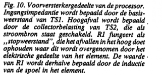
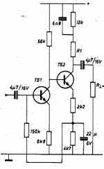
but I could not understand from the text what should be R1 resistance to get right electronic damping at the input and right falling the correction curve...
Do you know the formula?
I am a bit lucky too to understanding Dutch a bit
but I could not understand from the text what should be R1 resistance to get right electronic damping at the input and right falling the correction curve...
Do you know the formula?
Attachments
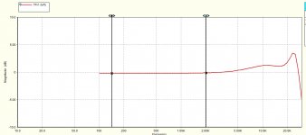
Hi George, thanks. I can't explain this: the resonant peak frequency, unless it is compound, is not at the LCR resonant frequency, yet the test with cart in air (essentially mech resonance free) show the same result (implying LCR is all there should be)........This is manual spot frequency measurement across the coil of an Shure M97XE.
An 100 Ohm Ro signal generator with a constant 4.91mVrms output, wired in series with the cartridge, feed a Hagerman Bugle RIAA preamplifier.
Cartridge:R:1K55, L:700mH.
0 dB refers to the measurement at 1KHz.
The collected data remained the same on all cases of cartridge position (Cartridge On Air, Cartridge lowered Onto Groove, Brush lowered, Brush raised, Stylus Force varied from 1 to 2 gr).
I guess the shown resonance is of electrical nature.
George
I wonder whether, somehow, your experiment measured the self-resonance of the coil ? ie the coil's own inductance and self-capacitance in isolation ?
LD
I think the whole point is that it is more complicated than that. The electrical and mechanical circuits work together, in this case I assume there is a mechanical resonant peak that works in concert with the electrical roll-off.
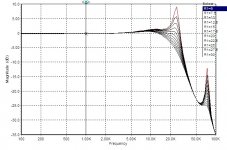
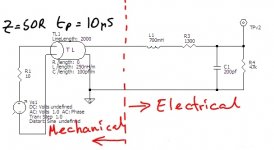
Here's a simple spice model for both mechanical and electrical aspects of a MM cartridge that produces readily recognisable results.
Mechanical system is modelled as a transmission line, with a delay appropriate for propagation as transverse wave along a cantilever, terminated by an appropriate mismatch. Electrical LCR system is modelled as just that, and coupled to the mechanical system.
A basic spice schematic is sketched below, marked up with the mechanical/electrical systems. Also attached is the simple f response for that circuit, and also a further developed model that shows MM loading variation working as it should re the overall f response.
The basic model has a lossless TL, whereas in reality there are losses, as there are in the generator. Easy enough to add to the model - try it !
I spent a happy few months a few years back playing about with models for Ortofon and AT carts, but also did a SaS/Shure V15 which I'll try to find. I rapidly became certain this model can mimic reality very well, so much so that it probably is what is really going on IMO.
Interesting?
LD
Attachments
Last edited:
- Home
- Source & Line
- Analogue Source
- mechanical resonance in MMs