Pyramid, one more favor, do you have part numbers and source for the 16 pin sockets and the ribbon cable
Thanks Greg
The socket from Digikey is PN ED3016-ND.
The cable from Digikey is PN H8PPH-1618G-ND.
The socket is fairly generic and can be found almost anywhere. The cable is also common, just be sure the IDC connectors on reversed (pointing in opposite directions) on each end.
Hi Pyramid
since you have been so very helpful sorting me out .. I'm going to order all small bits and pieces now..the main SG4 PCB you made a Mouser shopping list = suits me fine wrt Denmark ordering/shipping.
Now the rotary PCB needs " 4013 dual D flip-flop "..and mouser has them
http://www.mouser.dk/Semiconductors...-55d5e?P=1z0t4fpZ1z0z7pt&Keyword=4013&FS=True
but which SMD footprint to take?
thanks again
....
If you go with the rotary encoder, you might want to purchase the PCB for mounting the switch and parts:
[url]https://www.oshpark.com/shared_projects/AbsVI39H[/URL]
It uses surface mount parts, but you only need the IC and the 2 caps (0.47uFd) if you use the Arduino rotary switch (3 R's on on the switch already). You can also use the RA header that comes with the switch.
The rotary PCB needs "4013 dual D flip-flop"..and mouser has them, but which SMD footprint to take?
The PCB is laid out for an SO14 pkg IC. The caps are 1206 (3216 metric) and the Rs are 0805 (2012 Metric).
is this how you did your boards?
I have never soldred parts this small or surface mount parts before
https://www.youtube.com/watch?v=f0KZbhvKqS0#t=304.065878
I have never soldred parts this small or surface mount parts before
https://www.youtube.com/watch?v=f0KZbhvKqS0#t=304.065878
The video is a preferred or at least a good method, but for a few parts like this, not necessary.
I solder surface mount ICs by wetting one pad of the PCB layout (usually one of the corners) with a very small amount of solder, forming a slight "dome". Holding the IC with a tweezers, align all of the legs of the IC with the PCB pads while holding the IC against the PCB, sliding the pin over the wetted pad so everything is centered. Reflow the wetted pad so that pin of the IC is captive. Realign the part if necessary so all of the pins of the IC are centered on the pads. Solder the opposite corner of the IC to the pad by heating the pad and pin at the same time and applying solder where all three (pin, pad, soldering iron) meet. If the part is square and flat to the PCB, solder the remaining pins the same way, one pin at a time; if not, it can be re-centered by reflowing one corner at a time and shifting the part. If you bridge 2 pins, use solder wick to remove the excess. Using a small solder pen and small diameter solder (0.031" or smaller) is a must.
Solder the caps the same way: Wet one of the pads of the PCB. With a tweezer, hold the part in place against the solder dome and reflow it as the part slides into place. Reflow the other side of the cap.
Hi Bill
Got on the goodies need to get off my lazy butt and get this rotary encoder gizmo going. The ky-040 module I got has resistors R2 and R3 10k on it. It does not have R1. Is R1 needed?
Also if using the board plugging the 5 pins to the thru hole, do you need to bridge the R2 and R3 traces or are these parallel resistors?
In reading all the threads again I see if you need to set phase angle you will have to go to Sg4 board. I do not remember seeing how to adjust set down voltage. Might have to read thru again.
Well as always Thanks , you have been more than generous with your time and expertise.
Tom
Tom-
If R1 is missing, I would add it, either on the KY-040 module or the interface PCB. The resistors are in parallel, so do not add both.
Reduced voltage, phase adjustment and factory default need the buttons pressed before exiting standby, so those have to be done using the buttons on the PCB and not the rotary encoder. I would put the switches on the SG4 and wire the interface PCB in parallel with them; it does no harm to do this. Generally, you will set the phase and voltage once (or very infrequently), so you do not need access to the buttons on a day to day basis, only when you find the need to change the settings.
Glad I saw this post.Hi Bill
Got on the goodies need to get off my lazy butt and get this rotary encoder gizmo going. The ky-040 module I got has resistors R2 and R3 10k on it. It does not have R1. Is R1 needed?
Also if using the board plugging the 5 pins to the thru hole, do you need to bridge the R2 and R3 traces or are these parallel resistors?
In reading all the threads again I see if you need to set phase angle you will have to go to Sg4 board. I do not remember seeing how to adjust set down voltage. Might have to read thru again.
Well as always Thanks , you have been more than generous with your time and expertise.
Tom
Looked at mine and it is the same way, no R1
....
Reduced voltage, phase adjustment and factory default need the buttons pressed before exiting standby, so those have to be done using the buttons on the PCB and not the rotary encoder....
could I add yet another single press button parallel across all SW (or those needed) to force phase adjust controlled from rotary /front panel?.. Thought making a small hole in front panel w this switch behind it.. like sometimes seen wrt a rest button.. to put a pin in and activate. As phase adjust is what I'd like to do on the fly w/o having to open controller box
thanks
You can parallel any or all of the momentary switches (UP/DN/STBY) while using the rotary control without a problem, but it defeats the purpose of going to a single control. The rotary switch solution was meant to simplify the front panel and the interface, assuming the user would only need to set the voltage or phase initially or only occasionally afterward. Actually, it's difficult to imagine why you would change the phase (or voltage), once it is set for optimum? However, if this is something you envision adjusting often, then just put the 3 momentary switches on the front panel and forget about the rotary control.
... However, if this is something you envision adjusting often, then just put the 3 momentary switches on the front panel and forget about the rotary control.
well I have to read more carefully how to enter the phase adjust .. do I need one button .. or more buttons pressed simultaneously (if more buttons = wanted to bridge them = so single button action only = small hole in cabinet to put in a pin or something to activate)
Don't want/ need the 3 buttons for ordinary operation..just want access to the phase adjust ..
I plan on using your board as a 'calibration board' in same box as Daniels full 2-phase controller (will make a switch between the two signals) .. when having found phase values on the fly .. write down those values and enter into Daniels controller via PC (as he does not allow for on the fly adjusts .. but he has a gentle freq ramp/up down I want to use)
The way the box is done it is a pain opening closing it. When assembled leave it
thanks
If you only want phase adjust, then you only need to add one extra momentary switch for the UP button. Phase adjust mode is entered by holding the UP button while exiting standby mode. You can exit standby mode using the push button of the rotary switch, but you cannot assert the UP button using the rotary switch. So add a single button for the UP function; press and hold it while pushing the rotary momentary switch to exit standby and you will enter phase adj mode.
Once in phase adj mode, you can use the rotary action to change the phase value and the push action (short press) to change between individual phases (90/120/240). Long press of the rotary push action saves the settings and returns to standby.
Once in phase adj mode, you can use the rotary action to change the phase value and the push action (short press) to change between individual phases (90/120/240). Long press of the rotary push action saves the settings and returns to standby.
OK I found the instruction manual for the Sg4. It is in the assembly PDF at the end. I built it 6 weeks ago so I forgot Bill had put in all that information. Not as much fun as the Chinese stuff you get with zero information and you get to play 3d chess with Spock to make it do something!!!!!!
Tom
Tom
Glad I saw this post.
Looked at mine and it is the same way, no R1
Three resistors may not be necessary, it depends on where R1 is connected. The momentary push button action of the rotary switch does not require a pull up resistor (it won't hurt if there is one, just not required). The 2 quadrature signals when the control is rotated MUST have pull ups, either on the KY-040 board or on the interface PCB. These 2 signals also MUST have the caps installed on the interface PCB or you will get random results.
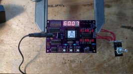
Houston we have lift off!!! Got the rotary switch on the Sg4 and it works like a champ. Push the button goes to 60 Hz turn nob goes up or down. What is really cool is when you turn it off it saves what ever frequency you had on the screen. This is not Bills 1st rodeo.
Well still have to hook up to my current power generator and build an enclosure but what cool set up this Sg4, with the rotary switch, is.
Thanks again Bill
Well still have to hook up to my current power generator and build an enclosure but what cool set up this Sg4, with the rotary switch, is.
Thanks again Bill
Attachments
Pyramid, I also would like to thank you for all the time, thought, and effort that you put in for this SG4 motor controler project. And also going the extra mile putting together all the information together that even a caveman should be able to build one. Also a thanks to all the other mentors in the DIY community from this DIY wannabe.
So to put all the odds in my DIY favor of replicating this controller I ordered all the same parts that Pyramid had to assemble a working unit down to the case.
While waiting for all the parts to arrive I was able to assemble the SG4 first and testing U3 pin 16 showed 5VDC and testing U2 pin 4 showed it is at 8VDC. The MK145 showed up and I was able to swap out the 22K resistors with the 2.2K resistors. With the rest of parts showing up I was able to finish assembly. So now to testing assembled unit.
Using a Variac with a Kill-A-Watt meter to plug the motor control in to help control any collateral damage along with Fast-Blo fuses. Working up to 125v meter showing .16 amps 7.9 watts in standby mode. With standby turned off only change was watts usage went up to 8.6.
But having problem with AC output at 92.7 volts.
Rest of voltage readings starting with the two power transformers. The one going to power Amplifier is 125v and output is 15.28v to each side of amplifier input. Next power transformer is the wall wart going to the SG4 input. 125v to wall wart and 12.19vdc at input on SG4. From the output of the SG4 to input of power Amplifier is 2.5vdc. From the power Amplifier to the step up transformer left channel 6.208 and right channel 6.21 then output side as stated above 92.7. All measurements were in default mode and double checked the step down voltage option and was indeed at 128.
So before chasing my tail looking for any assistance in explaining to this caveman what may be happening please. The only thing logical I'm thinking are the 2.2k resistors.
Thanks to all and a shout out to twystd for all your help also.
Unable to upload pictures something to do with security token.
This is the finished motor controller using the SG4 sinewave generator, LM3886 based MK-154 stereo amp, 2904 enclosure and rotary encoder switch. The 2904 enclosure comes with the mounting holes for the on-off switch and the main control knob so only the display window and toggle switch for 33/45 RPM was added to the front panel. The back panel of the enclosure comes with an IEC input socket with built in fuse holder, so only the NEMA 5-15 output connected was added to the back panel.
For the display window, I milled a 0.5" wide channel on the back side of the face plate. The depth was set to within 1/16" of the front surface. I then cut a 3/8" wide hole through the front panel and squared the corners with a file. This left a 1/16" wide lip to glue a plexiglass window into the face plate from the back side. The LED display would then be glued onto the window.
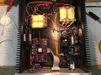
In order to remotely mount the LED, I soldered a 16 pin socket onto the LED pins as shown in the picture below. I also soldered a 16 pin socket onto the BACK side of the SG4 and connected the display to the SG4 using a 16 conductor ribbon cable with IDC connectors. In order to get pin 1 of the display to connect to pin 1 on the SG4, the cable needs to have IDC connectors mounted on OPPOSING sides at each end as shown in the picture below. The cable must attach to the BACK side of the SG4 and when plugged into the socket on LED display, the cable will exit to the top as shown below.
The MK-154 amp was mounted to the bottom plate using 1/2" stand-offs and the two LM3886 amps are attached to the heatsink as shown. The tabs of the amps are isolated, so no mica spacers are needed. Mount the amp to the bottom plate and mark where the holes in the LM3886 tabs meet the heat sink. Drill and tap holes for 4-40 screws into the heat sink for mounting the LM3886 tabs.
The transformers are mounted to the bottom plate of the enclosure and are connected as shown in the OP of this thread for 115VAC input/output single phase.
The rotary encoder and PCB are mounted in the main control knob opening and are wired to the SG4 as shown in the post on the first page of this thread.
I powered the SG4 from the wall adapter that is specified in the parts kit. I soldered wires from the input transformer primary to the wall adapter plug. The controller did not work properly if powered from the 18VDC on the MK-154 amplifier PCB as the start up surge cause the voltage to drop enough to put the SG4 into reset which caused another surge and the system was stuck in an endless loop. If you power the SG4 from the amplifier board, ensure the power supply to the SG4 is decoupled and filtered to prevent this.
Two wires connect the 33/45 RPM SPST toggle switch to the SG4.
There is a video of the completed controller Here.
Sorry for being ignorant, but I can not get my head around the explanation about powering the SG4.
I saved the pics and looked at them closely and do not see the wall adapter.
Any chance you could post a pic of all of the wire routing as finished?
- Home
- Source & Line
- Analogue Source
- 60 WPC Amplifier for DIY Turntable Motor Drive