Hi all, fine forum you have going here. I've been lurking for quite a while, lusting after the fine DIY TT some have built. I don't have anywhere near the system some of you have, nor the ear, but I do want to get the most out of what I do have.
I've got two decks that I don't find much info about around the web:
1) a sony PS-4750 manual direct drive. Speed control pots are a bit dirty, otherwise never had a problem with it, but I can't get styli for this oddball pickering cartridge.
2) Pioneer PL-41, belt drive, AC synchronous motor, runs a little fast, tone arm has no anti-skate controls, in great physical shape, old ADC series II cart.
So, the old sony works, but I need to change those pots. I've been using it for transfer of vinyl to CD at my computer. I'd like to use the pioneer for my listening system, but there are a few problems (speed, tone arm). Is this thing worth tweaking? Or should I give up on it, ebay it outta here & save for a Rega?
I'm presently working on a 120hz strobe circuit so I can verify the speed. I believe that I can make a OPA548 circuit work to provide decent control of a DC motor (some form of Maxon?), so I was thinking that would be the next step once I confirm my fast-running conditions with the strobe. However, is it worth the effort given the rest of this deck?
To make it more interesting, this tone arm bugs me a bit. When I gently lower the needle to the vinyl, the lead-in practically whips the needle over the first few grooves, a revolutions into the first cut. If I set it to 0 grams, the arm will float half way between lead-in and runout. I read somewhere this is correct for an arm without anti-skate controls. However, this setting really seems to be causing the jump that occurs when I drop in the lead-in. Does this tonearm stink? If its worth while to upgrade the arm on this deck, where do I start? I am definitely on the low end $$$ wise...
Thanks in advance for any feedback any of you may have.
Mark D
I'd rebuild the PL41, with a replacement arm, new cartridge.
I'm puzzled as to how an AC sychronous would run slow.
Remember the Rega 2 is just a great arm bolted to plank of
wood (formica'd lowish density fibreboard) with a MDF platter.
the turntable part isn't that great.
") sreten.
sreten.
I'm puzzled as to how an AC sychronous would run slow.
Remember the Rega 2 is just a great arm bolted to plank of
wood (formica'd lowish density fibreboard) with a MDF platter.
the turntable part isn't that great.
sreten.Thanks for the input.
Actually, it's slightly fast, not seriously fast. There is a switch for 50/60Hz as there is another for the voltage selection. The 50/60hz switch is wired to another tap on a large cap, I should probably sketch out the wiring sometime for my own edification. It's set to 60, but maybe that cap is shot.
There are 2 pullies, a smaller one for 60hz & a larger for 50. I have the smaller one in place. At one time I was thinking of having the pullies turned down to fix the speed problem, but that seemed like a real ardous trial and error process, especially without the tools to do the work...
I'm still thinking conversion to a DC motor makes sense, but I need to figure out some sort of pully.
Mark D.
I'm puzzled as to how an AC sychronous would run slow.
Actually, it's slightly fast, not seriously fast. There is a switch for 50/60Hz as there is another for the voltage selection. The 50/60hz switch is wired to another tap on a large cap, I should probably sketch out the wiring sometime for my own edification. It's set to 60, but maybe that cap is shot.
There are 2 pullies, a smaller one for 60hz & a larger for 50. I have the smaller one in place. At one time I was thinking of having the pullies turned down to fix the speed problem, but that seemed like a real ardous trial and error process, especially without the tools to do the work...
I'm still thinking conversion to a DC motor makes sense, but I need to figure out some sort of pully.
Mark D.
This sounds strange, do You have interchangeable pulleys? If the tt has a switch for 50/60Hz operation there would be no need for different pulley diameters. Your not talking about a stepped pulley, two different size "tracks" on the pulley wheel? If so thats for 33/45 rpm operation.There are 2 pullies, a smaller one for 60hz & a larger for 50. I have the smaller one in place.
The only possible function of the 50Hz/60Hz switch is to change
the value of the phase shifting capacitor - given it has this switch
then the pulley must have 50Hz/60Hz steps on it.
There is the possibility it is an asychronous AC motor, which,
unlike a synchronous AC motor, allows minor speed adjustment
via some sort of braking / variable friction mechanism.
(Garrard 301, Garrard 401, Thorens TD124 use this system)
If so, and the mechanism is not functioning it would run too fast.
Looking at the size of the motor, asynchronous is possible.
sreten.
the value of the phase shifting capacitor - given it has this switch
then the pulley must have 50Hz/60Hz steps on it.
There is the possibility it is an asychronous AC motor, which,
unlike a synchronous AC motor, allows minor speed adjustment
via some sort of braking / variable friction mechanism.
(Garrard 301, Garrard 401, Thorens TD124 use this system)
If so, and the mechanism is not functioning it would run too fast.
Looking at the size of the motor, asynchronous is possible.
sreten.Attachments
Darn, sreten, where'd you find that picture? I swear I saw it once, shame on me for not bookmarking it.
The manual & a sticker on the plinth both clearly indicate the motor is a "4-pole hystersis synchronous motor". The only friction related item I could think of would be in the bearing. It appears to be designed to be filled with some oil, but is quite empty. Maybe there is less drag without the oil?
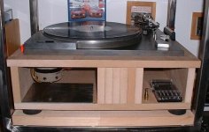
The two pullies are stepped for 33/45 operation. From the picture you can see the buttons on the upper left cover. These guide the belt from one step to the other. There is actually clip under the platter to hold the extra pulley. I have tried the other pulley, on both diameters, just to make sure I didn't miss something; it wasn't even close.
The manual & a sticker on the plinth both clearly indicate the motor is a "4-pole hystersis synchronous motor". The only friction related item I could think of would be in the bearing. It appears to be designed to be filled with some oil, but is quite empty. Maybe there is less drag without the oil?
The two pullies are stepped for 33/45 operation. From the picture you can see the buttons on the upper left cover. These guide the belt from one step to the other. There is actually clip under the platter to hold the extra pulley. I have tried the other pulley, on both diameters, just to make sure I didn't miss something; it wasn't even close.
g13092 said:
I'm still thinking conversion to a DC motor makes sense, but I need to figure out some sort of pully
If your PL41 is indeed the same as the pro-model pictured above then you might need an awfully big DC motor. Do you know if the platter is free-running, or braked in some way?
I can't understand how an asynchronous motor can be used in order to get a fixed fixed speed. Can ayone elaborate on this brake system of the Garrard?
I suppose that would be kind of getting higher slip at no load condition, and something that relax the brake when higher torque is required, but seems to me difficult to implement with mechanical devices.
BTW, nice tt you have there, sreten.
Werner, you always can buy a low voltage synchronous motor and build an oscillator and amp box. It's worth the (small) effort.
Raka said:I can't understand how an asynchronous motor can be used in order to get a fixed fixed speed. Can ayone elaborate on this brake system of the Garrard?
I suppose that would be kind of getting higher slip at no load condition, and something that relax the brake when higher torque is required, but seems to me difficult to implement with mechanical devices.
BTW, nice tt you have there, sreten.
Werner, you always can buy a low voltage synchronous motor and build an oscillator and amp box. It's worth the (small) effort.
Hi Raka,
Yeah I wish ! the source of the picture is :
http://www.straceny.de/Museum/Pioneer_PL41/pioneer_pl41.html
I have a SystemDek IIX with Rega RB250 / Ortofon MC15 Super MkII.
I've done a litttle reading into asynchronous AC motors.
The fundamental difference between the two types is
synch operates with a variable slip angle - locking it to
the incoming frequency whilst asynch operates with a
slip speed - typically a few % below incoming frequency.
A synch motor is fundamentally immune to AC voltage variations
whilst asynch is not, both types are linked to the incoming mains
frequency, but the asynch is not tied to the incoming frequency.
edit.........
Of course if you make the power supply have variable frequency
you can remove the brake mechanism and speed adjuster.
sreten.
(To be strictly accurate the asynch motor operates with a slip
frequency, the difference between driving frequency and
operating frequency varying with the load and I assume the
amount of current driving the motor as this determines the
motor magnetic field strength.
I also assume that drawn power is constant for an asynch motor,
unlike a synch motor which draws more power with slip angle and
load - this is the basis of its excellent stabililty)
So say an asychronous motor frequency is a little fast say 3%.
The 401 uses a rotating disk with a U magnet that can be moved
across it as a variable brake (like an electricity meter in reverse).
The brake sets the speed to 0% and additional braking
can increase this to a max of say -4%, 7% motor slip.
sreten.Attachments

Hi Sreten,
Thanks very much for the explanation.
Well, actually an induction motor is usually around 3% slower than synch speed.
I'm not sure is this is also for one phase motors, but for 3ph ones, the current drawn is VERY dependant on the load unless they are operated at constant flux (V/f=cte), with a frequency converter.
I still don't understand this brake thing. Is it making bigger the slippage for any reason? Is there any current sensing?
A hysteris synchronous motor appears to be a synchronous
motor but with permanent magnets built into the rotor.
(The other type being a reluctance motor, where the
rotors field is induced by the stator windings)
Characterisitics are lower losses, higher power.
Which would explain the size of the motor.
Personally I wouldn't give up the motor to save my life.
After a good clean and oiling of all parts if it still ran fast :
I'd use a small grind stone attached to something heavy
to stabilise it and align it perfectly vertical, to grind the
pulley to perfect speed, then polish.
sreten.
motor but with permanent magnets built into the rotor.
(The other type being a reluctance motor, where the
rotors field is induced by the stator windings)
Characterisitics are lower losses, higher power.
Which would explain the size of the motor.
Personally I wouldn't give up the motor to save my life.
After a good clean and oiling of all parts if it still ran fast :
I'd use a small grind stone attached to something heavy
to stabilise it and align it perfectly vertical, to grind the
pulley to perfect speed, then polish.
sreten.Raka said:Hi Sreten,
Thanks very much for the explanation.
Well, actually an induction motor is usually around 3% slower than synch speed.
I'm not sure is this is also for one phase motors, but for 3ph ones, the current drawn is VERY dependant on the load unless they are operated at constant flux (V/f=cte), with a frequency converter.
I still don't understand this brake thing. Is it making bigger the slippage for any reason? Is there any current sensing?
I'm sure a standard asynchronous motor at nominal torque
load does run around 3% below synchronous frequency.
In turntables I'm not so sure.
In the 401 the variable magnetic brake adjusts the slip
frequency of the motor by varying the load on the motor.
There is no need to sense the current.
Note the above graph shows slip frequency not angle.
I don't understand your reasoning regarding the current.
A synchronous motor does draw more current as slip angle
increases effectively locking it to synchronous frequency.
For an asynchronous AC motor this would not make sense.
I assumed it is being fed a constant current and the back
e.m.f. varies, varying the dissapation and power of the motor.
But I do not know much about asynchronous AC motors.
According to the 401 owner the motor runs very hot,
which agrees with a constant current power supply.
sreten.An asynchronous motor is fed by voltage, not current. The curve you show illustrates very well this. Being the voltage constant, the electrical power absorbed by the motor is directly dependant on the driven machine. This is why the motor gets hot if the rotor is locked, and melt if it's locked too much time. Actually this is the main failure reason for induction motors.
My question is how the magnetic brake knows that there are more current in the windings. Mmmm, I think it's like the higher the current the higher the brake effect. This could be sort of electromechanical coupling, yes, could be. This explains why the motor runs a bit hot, because the brake is increasing the slip, hence hte current. Yes, I think I got it.
The synchronous motors are always locked into the synchronous speed, if they get out of it, they stop. They only get the reference of the frequency of the mains, and the current that gets higher is the one of the DC field (for 3ph motors)
Personally, I would choose Synchronous motors with an oscillator, no doubt. Simple and effective.
BTW, do you have pictures of your systemdeck to share with us?
It's free running, no brakes.Do you know if the platter is free-running, or braked in some way?
Thanks for the link to the other pl41, sreten.
I suppose I could grind these pullies down, lots of trial & error for sure. So why would you stick with the AC over a DC motor? This AC has a definite cog effect, but I can't tell yet if it's audible.
Hi Raka,
The curve just shows torque output and slip frequency.
The magnetic brake adjust speed by adjusting the torque
output required.
Your statement that the motor is voltage driven does make
more sense than my assumption is it current driven.
I do agree a synchronous motor + variable frequency supply is
the way to do it.
Without a supply asynchronous is the only way to have variable
frequency (by a few per cent) whilst still being controlled by mains
frequency.
For a 401 owner removing the brake and having a
variable frequency supply is a reasonable option.
sreten.
(No photos of my HiFi at the moment)
The curve just shows torque output and slip frequency.
The magnetic brake adjust speed by adjusting the torque
output required.
Your statement that the motor is voltage driven does make
more sense than my assumption is it current driven.
I do agree a synchronous motor + variable frequency supply is
the way to do it.
Without a supply asynchronous is the only way to have variable
frequency (by a few per cent) whilst still being controlled by mains
frequency.
For a 401 owner removing the brake and having a
variable frequency supply is a reasonable option.
sreten.(No photos of my HiFi at the moment)
g13092 said:
I suppose I could grind these pullies down, lots of trial & error for sure. So why would you stick with the AC over a DC motor? This AC has a definite cog effect, but I can't tell yet if it's audible.
I wouldn't give up the original motor. the picture appears to show
a pulley on the right. It appears to be profiled to maintain the belt
in the centre of each pulley section.
Yes it would be trial and error, but as long as you can estimate
overspeed correctly not difficult. I'm still surprised it is overspeed
for a sychronous motor, it implies they all were, or that batch of
motor pulley's.
Simply try and get speed near enough, do not attempt to get it
bang on and you should be OK.
You only need to grind the central flat section, ignore the profile.
I'd rather build a variable frequency supply than give up the motor.
(My opinion of the latest fad for DC motors is unprintable,
and the fad was started by the deletion of the last high
quality synchronous motor suitable for turntables)
sreten.The value of the condensator doesn't adjust the speed, well, kind of allows for the starting, nothing else.
If the value is not the optimum, not the case if you haven't touched it, could be that the torque available is lower with some cap values, hence the current and slip variation.
BTW, could you measure the actual motor speed (rpm)?
And a power supply for tt is simple enough to build it. For synchronous or for induction motors. In my case, the motor had some low noise when switched on, no matter if running or not. Once my ps was build, no low noise could be heard even with sthetoscope. And here the distortion is about 3%, no more.
Induction motors are cheap and reliable, and can't say if the slip has some impact on sound, provided the inertia of the group is big, of course.
- Status
- This old topic is closed. If you want to reopen this topic, contact a moderator using the "Report Post" button.
- Home
- Source & Line
- Analogue Source
- update existing TTs or save pennies for a new setup?