It took me 2 min to redirect it when I made my first unit. Do you have vacuum desolder gun? Do not shave PCB or bend these pins.
I have a solder sucker but I find it always leaves a bit of solder behind, so desoldering a rigid assembly with 5 pins is very difficult. Anyway I already sanded down the SG4 encoder board edge a bit and gently bent the pins a hair, and when I put a straight edge across the mounting surface of the encoder it clears the SG4 encoder board (barely). With the addition of a washer I should be good to go.
I also need to file down the flat on the shaft very slightly to fit the knob I want to use.
Last edited:
Hi Alex,
You work is correct and the same I've done for mine.
If I've the time, I intend to do a back to back with straight pins to look more compact.
All in the pursuit of adapting these things to pro finish and best possible. My SG-4 controller with TDA8950 amp have been quite flawless operation for months now. Happy with it. However I do rarely find a bug, when switched on from cold, its sometimes the setting goes into Voltage adjust mode. I suspect its still something to do with this encoder thing. I didn't do anything or touch it before switching on, just switch on from last played.
As an added custom feature, I wired a momentary push button switch in parallel to the encoder push switch. I find it more practical using this switch.
Sorry for that long time for my response. Quite busy at work lately. My unit is also two month old and no issues, so far. It behaves as doc prescribed. I used Borns encoder with eBay board (just dumped Chinese encoder). One aspect must be mentioned, that encoder is a acting in reverse order. So, need to install it on the back side of PCB or to swop wires (Up as Down and vice versa). Pyramid warned and helped me to set my AB class amps and advices how to fix transformers buzz. Happy with that unit by now. It is on my Sonograghe TT made by Conrad Johnson. My next unit for my another TT made by Wilson Benesch will be with class D amp. Not sure yet if I’ll use two phase setup from the beginning since it will require to mod TT. I’ll see soon how to approach. Also, will try to create Arduino based soft to simulate encoder action to frequency for CLC. I really want close loop on that project. Without it, my speed is not tight stable and vary depending to cold or hot motor, beginning or mid or end of record, and etc. Let’s see how my time will allow me to start it.


I have a solder sucker but I find it always leaves a bit of solder behind, so desoldering a rigid assembly with 5 pins is very difficult. Anyway I already sanded down the SG4 encoder board edge a bit and gently bent the pins a hair, and when I put a straight edge across the mounting surface of the encoder it clears the SG4 encoder board (barely). With the addition of a washer I should be good to go.
I also need to file down the flat on the shaft very slightly to fit the knob I want to use.
I advice to all my friends to get one of these. If you are are in that hobby, then consider to acquire nice desoldering gun. It is very helpful and no solder left after its action.

You are not wrong, sir. I don't typically do much rework, but when you need to it's hard to beat the right tool. I generally do a project every couple of years, so it's a little hard to justify that tool, but then again I am a man so like spending money on tools. ") I have spent enough time with copper braid and a solder sucker, which is enough for things that you can wiggle a bit, but I have lifted a couple of pads tring to remove something like a switch, which won't move until all pins are completely free. Hence, if I can find a workaround I prefer it to desoldering things like header pin rows. Still, I should look for a decent deal on one of those desoldering guns.
I have spent enough time with copper braid and a solder sucker, which is enough for things that you can wiggle a bit, but I have lifted a couple of pads tring to remove something like a switch, which won't move until all pins are completely free. Hence, if I can find a workaround I prefer it to desoldering things like header pin rows. Still, I should look for a decent deal on one of those desoldering guns.
I have spent enough time with copper braid and a solder sucker, which is enough for things that you can wiggle a bit, but I have lifted a couple of pads tring to remove something like a switch, which won't move until all pins are completely free. Hence, if I can find a workaround I prefer it to desoldering things like header pin rows. Still, I should look for a decent deal on one of those desoldering guns.Assistance
Folks, I have completed the project without issue. Unfortunately, more often than not (and randomly) the amplifier module (TDA7492) starts going into melt down mode when one or more of the inductors start to oscillate with a clicking noise. This causes the output waveform to collapse essentially to nothing except for a fast paced spike without any voltage output. I am using a high quality Sure TDA7492 amp module. Interestingly, I have swapped out this amp module and replaced it with a more cheaper generic version of the TDA7492 module and have had similar results. So given that both modules behave the same way, opens up a pandora's box of what is the culprit issue could be! When it is operational, all voltages at the various points in the circuit are as to be expected, all waveforms are as expected (have an oscilloscope). I have considered earthing loop issues, I have considered output impedance issues of the brick transformer that I am using (not a toroidal). Anyway, any thoughts from anyone would be greatly appreciated. Thanks
Folks, I have completed the project without issue. Unfortunately, more often than not (and randomly) the amplifier module (TDA7492) starts going into melt down mode when one or more of the inductors start to oscillate with a clicking noise. This causes the output waveform to collapse essentially to nothing except for a fast paced spike without any voltage output. I am using a high quality Sure TDA7492 amp module. Interestingly, I have swapped out this amp module and replaced it with a more cheaper generic version of the TDA7492 module and have had similar results. So given that both modules behave the same way, opens up a pandora's box of what is the culprit issue could be! When it is operational, all voltages at the various points in the circuit are as to be expected, all waveforms are as expected (have an oscilloscope). I have considered earthing loop issues, I have considered output impedance issues of the brick transformer that I am using (not a toroidal). Anyway, any thoughts from anyone would be greatly appreciated. Thanks
Assistance - Continued
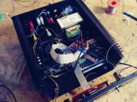
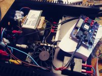
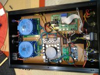
Thanks for the response. A little more detail. Firstly, with or without load on the output transformer, initial triggering of the oscillation still can occur. I have included a couple of photos to give you an idea of component layout. The power supply amp module is rated at 24V DC @ 3.2 AMP. (Turned down to 20V due amp restrictions at higher DC voltages due to low impedances on the output of the amp connected to the transformer output). The output transformer is rated at 100VA (2 * 12V AC inputs feeding a 240V AC main out). So roughly speaking the transformer at max capacity at 240 V can supply a .4Amp load. It should be noted that I have connected a standard 70W light bulb to transformer out and let it run for hours without issue ~ .3 amp draw. Of course when the oscillation begins everything shuts down. Final important point is the that disconnecting the transformer from the amp does stop the oscillation completely which leeds me to think about input impedances of the transformer. Specs on the amp state very clearly that the amp can only sustain at the lower end a 4 ohm Impedance load. I believe the transformer is presenting a lower impedance load than this, hence the amp runs amuk!! Of course my thoughts might be barking up the wrong tree completely. Any thoughts would be greatly appreciated. Thanks
Thanks for the response. A little more detail. Firstly, with or without load on the output transformer, initial triggering of the oscillation still can occur. I have included a couple of photos to give you an idea of component layout. The power supply amp module is rated at 24V DC @ 3.2 AMP. (Turned down to 20V due amp restrictions at higher DC voltages due to low impedances on the output of the amp connected to the transformer output). The output transformer is rated at 100VA (2 * 12V AC inputs feeding a 240V AC main out). So roughly speaking the transformer at max capacity at 240 V can supply a .4Amp load. It should be noted that I have connected a standard 70W light bulb to transformer out and let it run for hours without issue ~ .3 amp draw. Of course when the oscillation begins everything shuts down. Final important point is the that disconnecting the transformer from the amp does stop the oscillation completely which leeds me to think about input impedances of the transformer. Specs on the amp state very clearly that the amp can only sustain at the lower end a 4 ohm Impedance load. I believe the transformer is presenting a lower impedance load than this, hence the amp runs amuk!! Of course my thoughts might be barking up the wrong tree completely. Any thoughts would be greatly appreciated. Thanks
Attachments
Hello Bill, how are you?
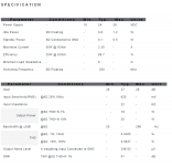
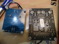
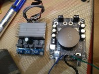
So, I was facing some issues with the regular TDA7492 board sold on Ebay and I've found a better built (Sure Electronics' webstore 2 x 50Watt @6Ohm Class D Audio Amplifier Board Compact - TDA7492) as I posted here a few months ago. It was finally delivered and I made the change today but I'm not getting the usual 120 VAC output, at 128 setting on the SG4.
The SG4 was running just fine, except for the TDA's shutdown issue when leaving stand by mode, forcing me to reset the power in order to make it run again. That's why I decided to replace it with a better board. The new board's specification are on the attached picture. I think (actually, I hope) it's just a matter of adjusting the gain board, but I have no idea how to choose the new resistors for the voltage divisor.
I've got a new multimeter, a real RMS one, and this is what I've got:
1) SG4 with everything normal, outputting 1.783 VAC on each phase/gnd pair;
2) Voltage divider with 1k8 and 8k2 resistors, with 0.315 VAC RMS on the 90+GND output and 0.320 on the 0+GND output;
3) TDA board outputting 6.93 VAC and 7.01 VAC for 90 and 0 phases;
4) Transformers outputting 56.5 VAC on the 90+GND, 55.9 VAC on the 0+GND and 81.3 VAC on the 90+0, with the SG4 set on 60Hz with voltage attenuator set on 128. On 81 Hz, the measurements are pretty much the same.
Except for this small issue, the Sure TDA board is a great improvement. No more crashes when exiting stand by or changing between 33/45. At least with the multimeter, I hope that this does not change with the motor plugged in.
Please, what should I do to get the correct voltages in order to power the 120 VAC hurst motor?
Attachments
The best method would be to replace the fixed voltage divider with a stereo pot so you can adjust the output.
Using the numbers you gave me, if you keep the 8K2 resistor, change the 1K8 resistor to 5K (2x 10K in parallel or 4K7 plus 270 in series). That should get you fairly close to 115VAC output.
Using the numbers you gave me, if you keep the 8K2 resistor, change the 1K8 resistor to 5K (2x 10K in parallel or 4K7 plus 270 in series). That should get you fairly close to 115VAC output.
Thanks for the reply, Bill!
Unfortunately, I do not have any stereo pots here, only mono ones. I do have a lot of resistors and voltage divider pcbs I had made.
Using a 5k6 and 8k2 combo I managed to get 115.3 and 114 VAC from 90+GND and 0+GND, I guess that's enough to get the motor started right?
(I will reduce the attenuator to get 98V)
Later this year I will build the MA3D board to use with the BLDC motor.
Thank you very much, Bill!
Further Help
Following up on my tails of woe, I have now put a pot in to represent the voltage divider. Playing around with the pot control definitely triggers the runway amp oscillation as the voltage on the output of the amp rises. The output stage of the amp needs to be around 12-13V AC RMS, however oscillation triggering comes in around about the 8-9V AC mark. Still open to suggestions. Everything at the moment is pointing to some problem with the output transformer presenting a load that the amp cannot sustain ..... I am open to suggestions guys
Thanks
I'm pretty sure you're right. I had a similar problem when trying to power a Papst 3 phase motor (up to 20W per phase); in the end I added an NTC thermister NTC 5D-9 between each amp output and transformer.
You may well need a different value thermister owing to the amp/transformer characteristics, they are cheap and easy to obtain and this is the easiest way I found of eliminating startup problems.
You may well need a different value thermister owing to the amp/transformer characteristics, they are cheap and easy to obtain and this is the easiest way I found of eliminating startup problems.
Ralph,
Thanks for your thoughts, didn't think to add a thermistor into the circuit, did however consider putting a high wattage 5 ohm resistor in series to up the overall impedance presented to the amp output from the transformer. Your idea is alot better. Will let the community know the results, once I have carried out. Have already source an appropriate thermistor from Ebay
Thanks
Thanks for the response. A little more detail. Firstly, with or without load on the output transformer, initial triggering of the oscillation still can occur. I have included a couple of photos to give you an idea of component layout. The power supply amp module is rated at 24V DC @ 3.2 AMP. (Turned down to 20V due amp restrictions at higher DC voltages due to low impedances on the output of the amp connected to the transformer output). The output transformer is rated at 100VA (2 * 12V AC inputs feeding a 240V AC main out). So roughly speaking the transformer at max capacity at 240 V can supply a .4Amp load. It should be noted that I have connected a standard 70W light bulb to transformer out and let it run for hours without issue ~ .3 amp draw. Of course when the oscillation begins everything shuts down. Final important point is the that disconnecting the transformer from the amp does stop the oscillation completely which leeds me to think about input impedances of the transformer. Specs on the amp state very clearly that the amp can only sustain at the lower end a 4 ohm Impedance load. I believe the transformer is presenting a lower impedance load than this, hence the amp runs amuk!! Of course my thoughts might be barking up the wrong tree completely. Any thoughts would be greatly appreciated. Thanks
Sorry for the late response, I missed your post.
What size motor are you using? The 100VA transformer is most likely your problem; it is too large for the class D amp you are using. These chip amps have over current protection that trigger much faster than their class AB cousins. The core magnetization of the xfmr can cause excessive current at start up; the larger the xfmr (and core) the higher the surge current at start up.
Your options are:
Use a smaller xfmr closer to the power rating of the motor.
Use a larger class D amp that has a higher threshold for over current protection.
Add ballast resistors (or thermistors) in series with the amp output to limit the start up current. These will reduce available voltage, consume power and dissipate heat and are the least efficient solution.
Pyramid,
Thank you for the reply, much appreciated. Yes I have essentially come to same conclusion.I will initially try a couple of thermistors (5 ohm / 3Amp) as an initial test, if this fails will swap out the transformer for a more efficient toroidal one. I will report back to the forum on results ... again thanks
Thank you for the reply, much appreciated. Yes I have essentially come to same conclusion.I will initially try a couple of thermistors (5 ohm / 3Amp) as an initial test, if this fails will swap out the transformer for a more efficient toroidal one. I will report back to the forum on results ... again thanks
I installed a pair of 0.22ohm (0R22) 5W wirewound resistors in series with the amp output to transformer. Since I can get most values at my place as easy as buying candy, I think I tried a higher value but got some unexpected results, can't recall what. I settled on 0R22 and that's it. Since my output transformer is 2 x 115V (series for 230VAC), I grounded the center tap for a balanced mains output. I didn't leave the output floating. Its been months, flawless operation so far. My output transformer is 60VA toroidal. Same with the one powering the TDA8950 amp which I added on a slim PC fan onto the heatsink. This made the SC really run very very cool in my tropical weather.
Last edited:
I observed some glitch on my unit fist time today. It could be just my setup and you guys have not seen same .... But any way, please share with your fixes if you did see the same behave.
I see my frequency is running up very quickly, sometimes right after I move from STBY to ON and sometimes after I use the encoder to adjust need speed. One encoder touch&clink is stops that. Sometimes I'm trying to use encoder to move frequency up or down, and is drops or increases for 1/2/3 digits and count runs up quickly again till I click.
I use Bourns encoder with 3 SMD resistors China made eBay board. I assume that some oscillation is going on, but I did not use Scope yet to see the actual cause. You might already saw same and fix that thing. So, please let me know.
Hi Alex,
This fault can happen and I don't have any answer why it can intermittently happen. I installed a separate momentary push button (parallel to encoder switch terminals) and use that instead of encoder push button. Can even remote that switch to near the table if required. I'm actually about to implement that, just thinking how to do a nice looking switch assembly.
This will happen if one of the encoder lines is staying low. Both lines from the encoder need to idle in the off (high) condition when the encoder is not being turned. The lines should only pulse low when turned.
If one of the encoder lines remain low, one of the outputs from the PCB will also stay low which has the same effect as holding the up or down button (the frequency will increase or decrease starting at 7 times per second an increasing to 20 times per second the longer you hold it.
The encoder switch is most likely sticking and not settling in the detente position.
- Home
- Source & Line
- Analogue Source
- DIY 4 Phase Sinewave Generator for Turntable Motor Drive